I've taken a few weeks to absorb this, to go back to your previous posts, and to try and determine how your responses can help me to fill the gaps in my understanding, so I've documented my full thought process as well as my eventual realisations - at least it can provide a historical record for me and maybe answer some of the same questions others may have after reading this thread. If you'd like to respond, some of my latter comments may address some of the things I was originally having problems with comprehending so you may like to just reference those as being the correct interpretations. Hopefully it isn't too disjointed.
Quote:
Originally Posted by fe1rx

Quote:
Originally Posted by 135
The Static Spring Load was calculated at 3600 N (or 810 lbs), i.e. the Static Spring Compression (60mm) multiplied by the Ohlins Spring Rate (60 N/mm). You then used this 3600 N value in the spreadsheet calculation for the Ohlin springs. You then went on to use the same 3600 N value in the spreadsheet calculation for the Swift 65mm 7" 60 N/mm springs.
Since the Static Spring Load was originally calculated based on the compressed spring height of the Ohlins spring (i.e. 60mm), I thought the Static Spring Load would have to be recalculated for the Swift springs because, for example, the Swift spring at 178mm free length may only need to be compressed by 15mm, resulting in a 163mm static spring length at ride height. This 15mm compression would result in a Static Spring Load of 900 N/mm (157.61 lbs/in), which is far from the 3600 N/mm Static Spring Load used.
Also, I'm not sure whether the top mount height should factor into a comparative measurement, i.e. the 26mm difference in top mount height (70mm OE vs 44mm GC plates) could be considered against the Swift springs compressed height of 163mm (in my example) giving a comparative measurement of 137mm (178-15-26mm) against the 140mm OE Top Mount based measurement (200-60mm), meaning a relatively like-for-like comparison.
Again, I'm confused.
Why is the same Static Spring Load used for both springs?
Maybe another question is, why does the Swift 7" spring still need to be compressed by 60mm?
|
To clarify, the "static compression" is the total spring compression from its free length when the car is sitting statically (not moving) on the ground. That spring is supporting its corresponding corner weight, less the unsprung weight, but it is doing so with a motion ratio which increases the weight supported by the spring relative to the sprung weight supported by that wheel. The static compression includes whatever preload you put into the spring when you installed it - perhaps that is what you are missing in your thinking? Every 60 N/mm spring will have a static compression of 60 mm at a load of 3600 N, regardless of its original free length. The only exception would be if you preloaded the spring to more than 3600 N, in which case it wouldn't move any further until you exceeded that preload. |
I am definitely not understanding something regarding how the static spring load is fixed at 3600 N. I can understand it being a product of a given static spring compression and spring rate but I don't understand how it can remain at 3600 N, particularly for different spring lengths - I thought that the static spring compression would have to differ from 60mm to maintain the same ride height with different top mount assemblies and even more so for different spring lengths.
While I don't have the hub mounting stands that you've constructed, I have remeasured my front springs correctly, while under normal vehicle load, with the wheels still mounted and the car sitting on the ground - I manoeuvred a tape measure into the wheel-well behind the wheel/tyre to sit flush with the spring. My measurements should be accurate to within 1mm. Below are those measurements:
General
178mm free spring length
70 N/mm spring rate (Swift Z60-178-70)
49mm top mount height (Vorshlag camber plates)
3mm spacer thickness (Swift thrust sheets x2)
Left
129mm static/compressed spring length
3430 N static spring load ((178-129)x70)
49mm static spring compression (178-129)
51.5mm exposed thread below the lower spring perch
328mm ride height (RHD car, no driver)
Right
134mm static/compressed spring length
3080 N static spring load ((178-134)x70)
44mm static spring compression (178-134)
50.0mm exposed thread below the lower spring perch
326mm ride height (RHD car, no driver)
For starters, even though it's comparing left and right, it's strange that a 5mm difference in static spring length results in only (i) a 1.5mm difference in the exposed thread below the lower spring perch and (ii) a 2mm difference in ride height. I would have thought that the difference would have been considerate of the 0.96 motion ratio and, therefore, equal to ~4.8mm.
That aside, the static spring load for each side differs and it also differs to your 3600 N value, which I thought there might be some correlation or relativeness even though it's comparing 70 N/mm and 60 N/mm spring rates.
You made a statement:
"Every 60 N/mm spring will have a static compression of 60 mm at a load of 3600 N". This makes me think that the static spring load is the known value from which others are calculated, which concurs with your spreadsheet calculations but it doesn't make sense to me considering the process that you used to initially determine that spring rate was dependent on the measurements for the free spring length, static/compressed spring length and spring rate, which implies the static spring load is the calculated value and, therefore, it should be recalculated for different height springs or springs that aren't compressed as much.
I can see how the conversion from static spring load to corner weight shows the relationship between the two and so 3600 N makes sense from that perspective, which means that force was required for that corner weight, which was a result of that ride height, which required that 60 N/mm spring to be compressed by 60mm to achieve that... but... I can't make the link between all that and how the static spring compression would still be 60mm when you changed from OE top mounts to GC plates that had different top mount heights or when changing spring lengths.
For the top mount change, I thought you would require 26mm less spring compression, which, for your 60 N/mm springs, would result in 1560 N less static spring load, that being 2040 N.
For the spring length change from 200mm to 178mm, I thought you would require 22mm less compression, which, for your 60 N/mm springs, would result in 1320 N less static spring load, that being 2280 N.
But then anything different to 3600 N static spring load would not result in the same corner weight.
This is what I mean... I understand most parts in isolation but not all in unison. The spreadsheet calculations make sense but I'm having trouble understanding the theory.
Speaking of the aforementioned spreadsheet, based on a 3600 N static spring load, I calculated what the values would be if the spring rate was changed from 60 N/mm to 70 N/mm (as is the case for my Swift springs) and it resulted in a static spring compression of 51mm (rounded down). For my springs, that have a free length of 178mm, this would result in a static spring length of 127mm, which is close to the 134mm (+4%) static spring length that I measured for my FR spring, which also has a 326mm ride height (without driver though), so I could see that the calculations roughly panned out but I was still stuck on why the 3600 N static spring load is fixed.
Lightbulb moment!
Now, I
couldn't make sense of any of this
until I realised that these linear springs are just obeying Hooke's Law, which states that "the restoring force
F needed to extend or compress a spring by some distance
X is proportional to that distance" and can be represented by
F = -kX
where
F is the static spring load,
k is a constant factor characteristic of the spring, i.e. it's spring rate, and
X is the static spring compression.
This restoring force (i) returns the spring to equilibrium, i.e. its natural state, (ii) is in the opposite direction to the applied force thats extending or compressing the spring, and (iii) is reflected by the negative sign on the right side of the equation.
Therefore, instead of solving for the restoring force, the equation can be changed to solve for the applied force, in which case, the restoring force would be negated resulting in the formula being
-F = -kX
or
F = kX
So, at least Hooke's Law helped me to understand the constant relationship between the static spring load, spring rate and static spring compression. I presume it also means that no single value needs to be considered fixed or known as they are all co-dependent and one value, e.g. static spring load, can initially be calculated from the other values and that calculated value can then later be used as the constant in the relationship since it will eventually be the other two values that will, or can, be variable.
By using various values in the spreadsheet, I can see that, if the spring characteristics remain the same and the top mount is changed from OE top mounts to GC plates, the ride height will remain the same if the lower spring perch location is changed by the same amount as the change in top mount height. But since that is outside the scope of the spring, Hooke's Law doesn't apply.
While writing this, I think I have made one further connection - based on your image below (as long as it is drawn to scale, which I believe it is considering your attention to detail), for a change in top mounts only, i.e. still using 200mm 60 N/mm springs, I now realise that, (i) the lower threaded portion of the strut assembly (where the lower spring perch is located) is in the same position, (ii) the different top mount assemblies
slightly affected (perhaps by 10-12mm, something similar to the height of the top nut) the positioning of the shock in that assembly (there is a visible height different between the top of the strut top thread, and various other points of the upper shock, in the two drawings) resulting in less shock compression at static ride height and (iii) the additional height gained from the GC plates allowed the lower spring perch to be raised for increased tyre clearance.
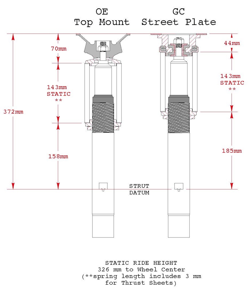
As a result, the static spring length is still the same to achieve all this, which means the static spring load is also the same.
But there was a slight difference between the top portion of the two drawings, so the question still stands, although, the values are not to the same degree: how can the static spring length still be 60mm when there is a 10-12mm difference after changing to the GC plates? I thought you would require ~15mm less spring compression, which, for your 60 N/mm springs, would result in 900 N less static spring load, that being 2700 N.
Possibly, due to the above-mentioned decreased shock compression, the shock has more length/stroke available before bottoming out and the spring could potentially have less static compression, resulting in more length/stroke available before coil binding (although, since the lower spring perch location was also raised to maintain ride height, the spring's potential has been negated at the "expense" of increased tyre clearance).
Has there just been a repositioning of the spring in the vertical plane and, therefore, the static spring length doesn't change?
Perhaps it's because the ride height is based on the overall static strut length and it doesn't really matter what the component measurements are, as long as the relationship between, and the measurements for, free spring length, spring rate, static spring load, static spring compression and static spring length remain the same or relatively the same.