135i Cluster Notes:
1. My 135i cluster (built in 2012) did not have any torx screws to remove. I just had to undo the plastic clips around the cluster to separate the halves.
2. To release the 18 pin connector from the back black plastic housing, there are 4 tangs at each corner of the connector on the PCB, use a thin screwdriver to depress the tangs while lifting on the black plastic and it will let go pretty easily.
Picture of tangs on the 18pin connector.

3. Release the ribbon cable at the bottom by pulling the corners of the black plastic locking strip away from the white plastic connector.
Picture of released ribbon cable.

4. Here's the orientation and location of the 8pin eeprom on the 135 PCB. My chip was a 160D0WQ.
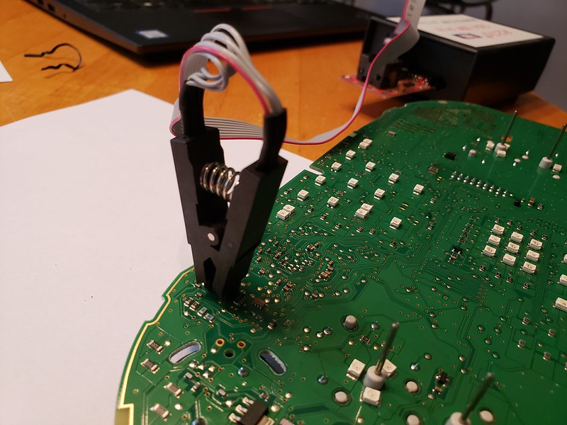
5. So I got everything apart and was hooking up the R270+ only to find out that 6 of the 8 U2 holes on the red board are filled in with solder. I desoldered the red board to get the connector to seat, everything worked correctly after doing this.
Here's how I connected the R270+/Red board

After that the .BIN read/writes were easy and quick. I still need to take it out to the car and code it.