My HPFP needed changing, here is my DIY.
Disclaimer: you do this at your own risk. Professional installation is encouraged.
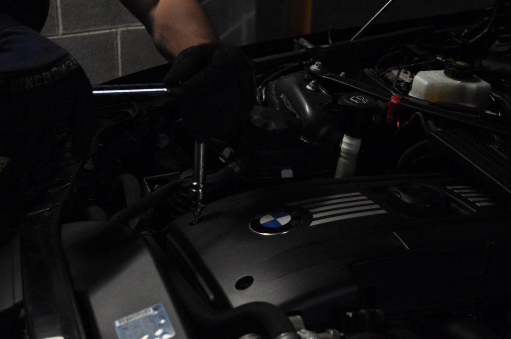
Estimated time: 6hours* (highly recommended to let the car cool down overnight. I basically removed everything besides the fuel pump during the night, then the next morning removed the fuel pump itself. This will let the pressure in the fuel lines subside a bit plus will reduce your chances of getting burnt)
Tools you will need:
8mm socket
10mm socket
11mm socket
5mm hex (short – i.e you’ll be using this in a tight *******
5mm hex (long – you’ll be using this to reach past other obtrusions)
T20 torx
T25 torx
E12 female torx
17mm OE spanner
18mm OE spanner
24mm OE spanner
Flathead screwdriver
Microfibre towel / shop rag
As of May 2015 the latest and greatest fuel pump part number is: 13517616170
You can order it from Tischer here
OK the HPFP replacement can be broken down into around 9 steps of varying difficulty:
1. Removing microfilter & cowl (very easy)
2. Removing airbox (very easy)
3. Removing chargepipe (easy)
4. Removing throttle body (moderate)
5. Removing engine cover (easy)
6. Removing intake manifold (moderate)
7. Disconnecting fuel lines (easy)
8. Removing fuel pump (moderate)
9. Putting it all back together
Step 1: Removing microfilter & cowl
Tools needed: 8mm socket & flathead screwdriver
- Unclip the small black cover on both the driver side and passenger side and wiggle the rubber grommets free from the cover.
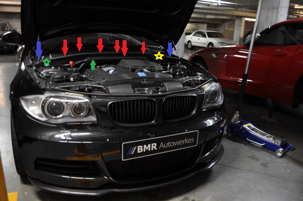
- Unscrew the 6 x 8mm bolts holding the microfilter down (red arrows)
- Unscrew the 2 x 8mm bolts holding the cowl in place (blue arrows)
- Disconnect the ambient temperature sensor by unclipping it (green star)
- If your car is fitted with an alarm, disconnect the alarm sensor (yellow star)
- Use your flat head screwdriver to unclip the part of the cowl that attaches to the cabling running through your engine bay (green arrow)
 Step 2: Removing airbox
Tools needed: Flathead screwdriver
Assuming you still have your OEM airbox, use your flathead screwdriver to pry open the 7 metal tabs holding the lid in place.
Then using your flathead screwdriver, unscrew the two collars holding piping in place (indicated by the red arrows)
The airbox should now just be held in place by three rubber grommets on the underside of the airbox, gentle rocking back and forth combined with a bit of a yank should free the airbox.
Now, disconnect the vacuum hose fitting indicated in the second pic in the red circle. Simply squeeze the sides together and lift up.

 Step 3:Removing chargepipe
Tools needed: Flathead screwdriver, T20 torx (and in my case 8mm socket)
I have an ER chargepipe, so if you’re still OEM, there’s another DIY for removal.
Unscrew the collar (blue circle) with a flathead screwdriver, unbolt the collar (red circle) with an 8mm socket. It’s likely your car will be different, but it’s not rocket science you’ll be able to figure it out
Then, up near the ‘top end’ of the charge pipe we need to remove an electrical sensor with our T20 (2 screws) indicated by the red arrows, and then use your flathead screwdriver to pry open the clip holding the chargepipe to the intake manifold. Wiggle the sensor out... if your chargepipe has a BOV, slide the vacuum line off the back of it. No pic right now but I’ll show you one later.

 Step 4: Removing throttle body
Tools needed: 10mm socket
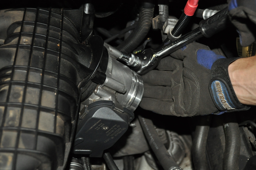
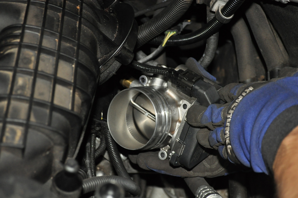
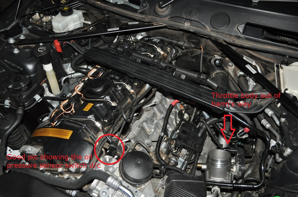
There are 4 x 10mm fasteners holding the throttle body to the intake manifold. Use your socket to undo them. There is also a vacuum line leading out of the back of the throttle body, squeeze and rotate this and it should come off. The last sensor is fairly obvious, however I couldn’t get mine undone. If you can, great, remove the throttle body altogether and keep it in a safe clean place. If you’re like me and can’t get it undone, just lay the throttle body to the side of the engine bay – there’s plenty of slack in the cable, and cover it with a cloth of some sort to prevent any debris from contaminating it.

 Step 5: Removing engine cover
Tools needed: TBA
4 fasteners. Undo them. Lift the cover off and remove gently. Done.
Note: some cars will have a crankcase breather line... mine didn’t so I can’t show you pics on it. If yours doesn’t have it, it will just be a plug like in the pic below. If you do have it, I don’t think it’s too hard to disconnect.
 Step 6: Removing intake manifold
Tools needed: T20 torx and 11m socket
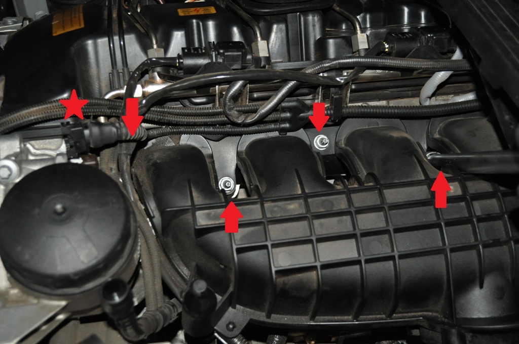
Let’s start with the intake manifold sensor, use your T20 torx to undo the 2 screws holding the sensor in place .

Then slide the wiring harness junction box off the bracket on the underside of the intake manifold.

There is an oil pressure sensor switch up near the oil filter (red star), so use your fingers/flat head screwdriver to undo this, keep the clip safe and lay the sensor to the side.
Grab your 11mm socket and undo 7 x 11mm fasteners holding the intake manifold to the engine block. In this photo I’ve marked the obvious ones with a red arrow, but you shouldn’t have trouble finding the others.
Removing the manifold itself can get a bit tricky due to space constraints... the piping down the back near the firewall will require a bit of a tug and pull away for the manifold to slide out. Once it’s clear though, it’s smooth sailing.

Your engine should now look like this
 Step 7: Disconnecting fuel line
Tools needed: 24mm spanner, 11mm and 17mm spanner (could be 18, I can’t remember), E12 female torx.
This is probably the most hazardous part of the install. The fuel is stored under quite great pressure... however I left the car overnight so when I undid it there were zero dramas, about a teaspoon of fuel dropped out and I had a microfiber there to catch it. For safety sake, undo the fuel line nuts very slowly and wear goggles/protective clothing.
Red circle: use your 24mm spanner to unscrew this fuel line pressure sensor
Green circle: unclips
Blue circle: E12 torx – undo this fastener
Yellow star: I’ve forgotten to take a good picture, but this is where you’ll find the two fuel line nuts, they’re pretty obvious. Undo them with a 17 (or 18mm – can’t remember) spanner. Do the left one first. Move the fuel line out of the way.

Next, use your 11mm socket to undo this fastener (red circle).
Use your 17mm spanner to again undo the fuel line nuts (blue circles). Move the fuel line out of the way.

 Step 8: Removing fuel pump
Tools needed: 5mm hex keys (long and short) and a microfibre towel
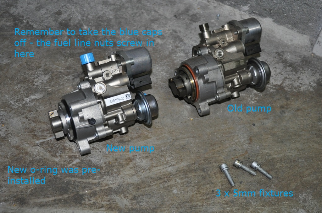
Now onto the fuel pump. There are 3 x 5mm hex fasteners holding the fuel pump in place.
In this pic, ignore that I haven’t removed the fuel lines yet, the pics are just a bit out of order...
You can see the red circle where you will need to use your 5mm hex key to undo the nuts... for the ‘back one’ i.e. closest to the engine block, use the long hex key and go around the fuel pump. You’ll figure it out.

Once the fuel pump starts to become loose you can gently wiggle it out... a bit of oil and fuel will dribble out here. Have your MF handy to clean it up. In my case, barely any came out.
Let’s compare old and new...
Where the fuel pump used to be. This is where the oil will dribble out to. I’ve since cleaned it up.
 Step 9.
And you’re done (well almost). Put everything back together in a similar fashion to how it was disassembled... you’ll figure it out.
The fuel line nuts should be torqued to 30nm but if you don’t have a torque wrench just do them tight, without applying excess force. Last thing you will want is to bend/break your fuel line.
Start her up – there will be a long crank as the fuel line repressurises and fuel goes through the HPFP for the first time, but then you should be good to go.
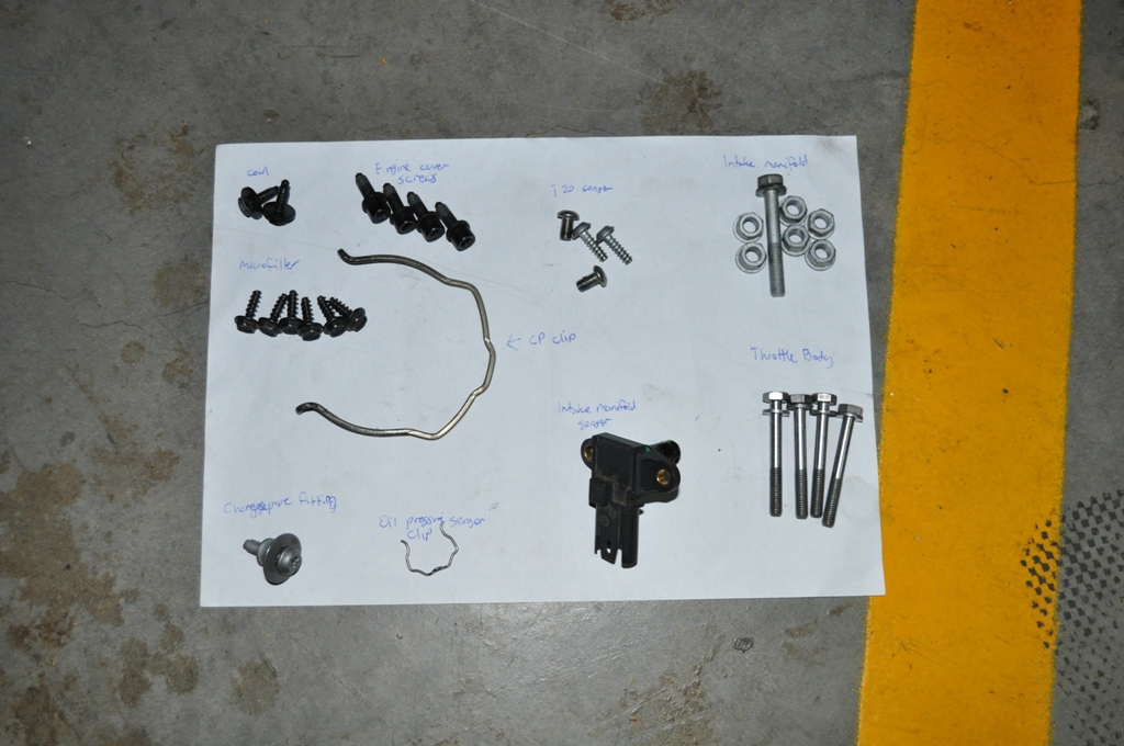
Whenever I removed a screw/nut/fastener I wrote it down just in case I forgot where to put it, here's my chart if it helps you: