After several weeks of monitoring and recent PPI, I found that I had slow leak on my Transmission Output Shaft Seal. I also had a leak at Rear Diff Pinion Seal, which I will tackle at later time. This DIY is for me to document my procedure and not necessarily the step by step tutorial. Please do your own homework, work at your own risk, and use this as reference only. If you guys find any mistake or better way to do it please mention it.
1. Remove the exhaust from down pipe all the way to resonator.
2. Remove the rear sub frame brace.
3. Remove the heat shield from the chassis.
4. At this point you should see the bolts that connect the Guibo to the Transmission Output Flange.
5. Loosen the 3 bolts. Before you remove it though, make sure you mark each bolt in one plane to the Output Shaft Flange. This to make sure that you have the same orientation to avoid any vibration.

I bought new bolts and nuts.
https://www.fcpeuro.com/products/bmw...s3-26117527475
https://www.fcpeuro.com/products/bmw...ut-26127536563
6. At this point you want to be able to rotate the drive shaft to get access to the all 3 bolts. In order to rotate the driveshaft, you need to unlock the parking shifter. I chose to do this from underneath the car by doing this step.

I removed the bolts but didn't slide the drive shaft out just yet.
6. I went ahead to remove the drive shaft as well, because I was going to attempt to replace the Rear Pinion Seal, but later found out that I couldn't remove the Pinion Nut.
7. To remove the Drive Shaft, you need to loosen the Insert Nut CW. This was super tough. I ended up heating the nut with heat gun before I was able to loosen it. You need to replace this nut after removal since the thread locker is build in the nut threads.
I bought this set which has all the necessary tools to remove the Insert nut and the pinion seal.
https://www.amazon.com/gp/product/B0...?ie=UTF8&psc=1
8. Once the insert nut is completely off the drive shaft, I proceed to remove the Center Support bearing bolts and support the entire driveshaft assy with Transmission jack.
9. Slide the Drive shaft out of the Transmission Output Flange.
10. Slide the Drive shaft out of the Rear Diff Pinion shaft.
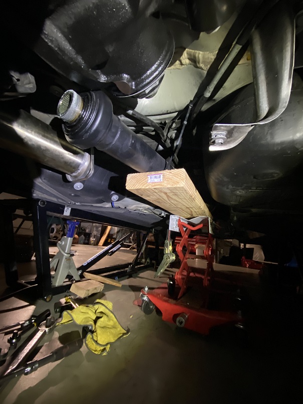
11. Now you can see the Transmission Output Shaft Flange.
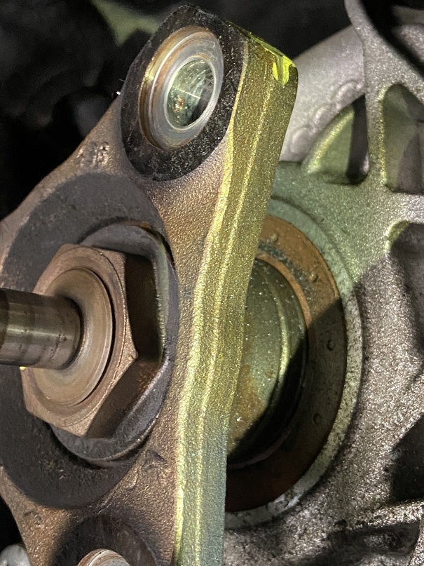
.
12. The Flange is press fit to the spline and you would need to brace the flange to remove the nut. This Giant nut (36mm) is Loctited so a little heat gun persuasion was necessary.
13. I marked the nut final orientation to the shaft just to double check that I get the torque spec correctly.
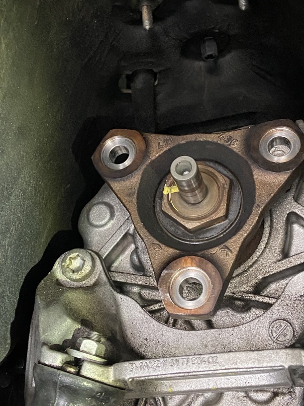
14. Other folks choose remove transmission mount to get better access to the flange to brace it, I decided to not remove the transmission mount and made a giant spacer that bolt up to the flange to brace it while removing the nut.

.
15. Even with heat applied to the nut, this thing was on there tight. I didn't want to use impact.
16. After a couple more heat cycle it finally came loose. I marked the the flange to the spline in one plane so I can put it back in the same orientation. I don't think you need to do this, but I'd just do it for ease of mind.
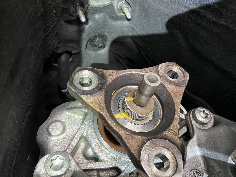
17. Pay attention to how flush the flange surface to the spline end. This will be your reference of the final engagement of the press fit between the flange and the drive spline.

18. You need a 3 jaw puller or similar device to get this flange off the drive spline.

19. You will hear it pop once the press fit was released.

.
20. Its time to remove the seal victim. Before I remove the seal, I'd measure the depth of the seal with respect to the housing. The TIS didn't mention this other than drive the seal till it hits a hard stop. To do this, I used a depth gage to measure how deep the seal is seated with respect to the housing edge. You can also visually see how the chamfer edge of the housing is almost flush with the edge of the seal front edge. My depth gage measured at .018"

21. To remove the seal, I opted to modify the smaller 3 jaw puller from the set I bought from the Harbor Freight, instead of using conventional pry bar style seal removal tool. I just didn't want to risk any damage to the housing at all.


21. Clean the mating surface with clean paper towel. Its time to put the new seal in.