Nice write up Chris!
I also do my own alignments, so if you don't mind I will share a few different ways I do mine.
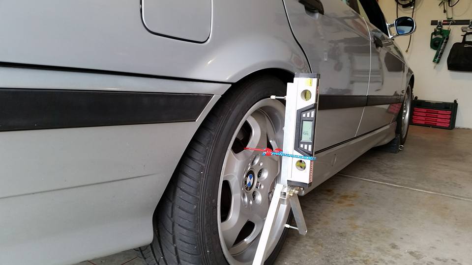
For camber I created a jig out of 1" square aluminum tubing which allows me to install a digital level. Having a flat surface to zero out the level is important for getting accurate camber measurements. If you are going to adjust camber, do so before you adjust toe since adjusting the camber will have an impact on the toe.
For measuring/adjusting toe I have used a few different methods. I first tried using strings on jack stands, but found it cumbersome and difficult to not touch the strings when making adjustments. Then there is also the issue of not being able to roll the car after an adjustment to settle the suspension since that would require a re-setup of the string parallel to the vehicle center line.
My solution was to attach the string to the chassis, in a similar way the "Smart String" system works....but substantially cheaper. This solution uses two Harbor Freight suction cups with 6" carriage bolts attached to them. The suction cups stick to the front/rear bumpers and put the bolts at the height of the center hubs. I then run fishing line between the bolts, using a tied loops on both sides of the string. The threads on the bolts help hold the orientation of the string in one place. Here is a picture:
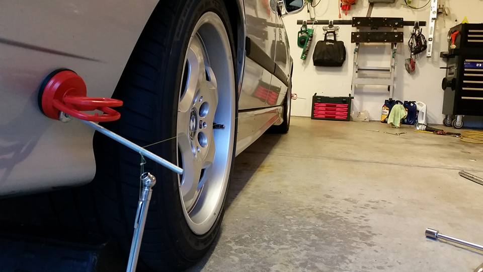
This string method works nice since you can roll the chassis after an adjustment without having to re-setup the strings. You do need to know the front left/right hub distance along with your rear left/right hub distance in order to orient the strings parallel to vehicle centerline. I use this suction cup string setup for detailed adjustments after a suspension/coilover installation. It is a little complicated, as it takes me roughly 3 hours to do a four wheel toe alignment using this method. There is a simpler/faster method though, which I will explain next.
The "quick" toe measurement/adjustment method that I use is similar to what Chris posted. My quick method involves using toe plates and a tape measure. The issue with toe plates is that you also need to check thrust angle for the rear. For checking thrust angle this is my process: my digital level has a red laser on it, and I aim my camber jig horizontally and shoot the laser to the front wheels (or back wheels if double checking front toe). I then place a tape measure to the hub of the front wheel and measure the distance between the laser and the hub. I do the same to the other side, and if these measurements are different, then the thrust angle is not zero. Do some trigonometry and you can figure out how much adjustment you need to make to the rear toe to get it where you want it. I don't have a picture of this process, but it is pretty similar to what Chris showed except the measurement is taken at the center hub instead of leading/trailing edge of the wheel and the laser is attached to the wheel.
Also note that if you are following Chris' process and measuring a 1/16" delta between the leading/trailing edge of the wheel, that would equate to a 1/8" of total toe at the axle.