As with the front, we have measured the rear chassis pickup point locations with ±1 mm precision.

Similarly, the rear upright dimensions are required with ±0.1 mm precision. This required removing the upright (wheel carrier) and fabricating appropriate spherical targets to measure to. The upper, guide and toe arm targets were fabricated from the cores of discarded ball joints.


Initially I found the centre of the camber cross-axis ball joint and trailing bushing using a pair of 1 ball bearings as targets.


Note that the OE location of the camber bearing in the upright is not centered in the lug. I call it outset from the center of the lug i.e. away from the center of the upright. The OE location of the trailing arm bushing is similarly outset. The ability to adjust the locations of the bearing and bushing in their respective lugs is a potential tuning parameter that I will explore later. To further that exploration, I needed to know not only the center location but also the orientation of the axis so that I can find the bearing center at any arbitrary inset/outset. This prompted me remove the bearing and bushing from the upright and to use a 2.25 diameter ball bearing as a target on each side of the lugs allowing me to find both the center of the lug and its axis.
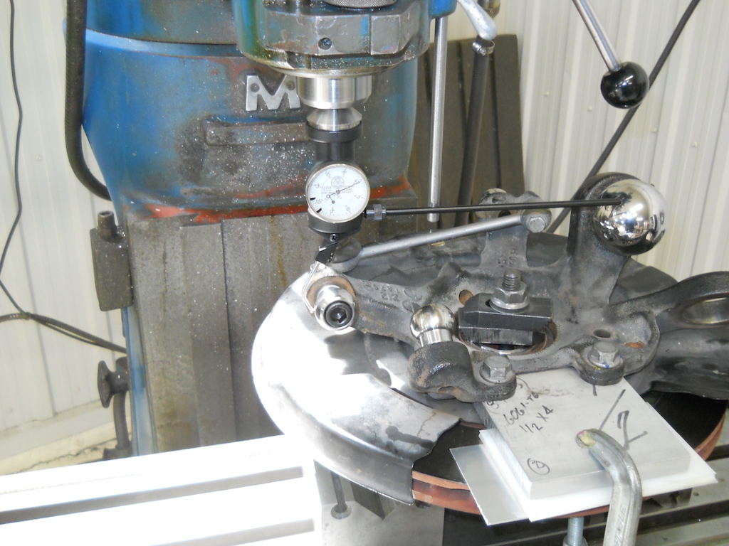
With appropriate targets installed, I found the upright Y dimensions of each target center using a height gauge and subtracting the target radius.

I found the X and Z dimensions using a dial indicator to center on each target and a vertical mill with a digital readout to locate the coordinates.
The kingpin points on a multi-link upright being virtual, there is no natural up direction (Z-axis) to the upright. I recorded the brake caliper mounting holes and used these to define a provisional Z-axis direction. I later used SusProg3D to solve for the virtual king pin points at design ride height and alignment. The final upright geometry was then rotated to make the king pin axis vertical in side view (i.e. zero caster) to properly define the upright dimensions at zero camber, caster and toe. To allow for further investigation on the effect of insetting or outsetting the camber bearing and trailing bushing I have included these dimensions.

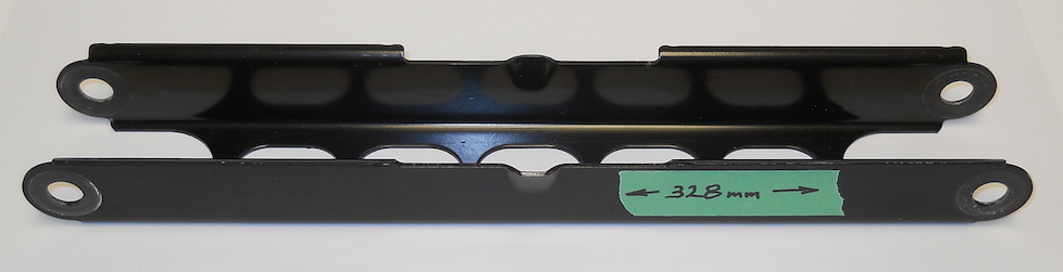
We also need to know the pin-to-pin lengths of each of the rear suspension arms.
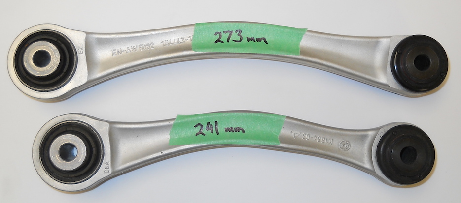
The camber arm has a nominal length of 400 mm, but this can be adjusted by means of an eccentric bolt to adjust camber. Accordingly, I treat it as a variable length arm.
The OE toe arm has a true length of 412 mm and its inboard mounting point is adjustable laterally by means of an eccentric bolt. Because I am using an adjustable length toe arm and have fixed the inboard mounting point, I am treating this arm as variable length also.
With these dimensions in hand we now have enough information to create a model in SusProg3D. I will follow up with a discussion of what that model reveals.