My goal is to install ride height sensors at all four corners that can be used to log ride heights. This data can be used for estimating aero loads, and to generate shock speed histograms for the purpose of damper tuning. Step 1 is choosing an economical sensor.
The motorsport go-to for measuring real-time suspension travel is a linear shock potentiometer. Typical examples are available from AiM and others:
https://www.pegasusautoracing.com/pr...Product=MC-206
Isa-Racing in Germany sells a clubman line of lower cost linear potentiometers at about half the cost of the premium motorsport versions. Reportedly these are environmentally protected to IP60 (dust) vs. the higher IP65 rating (dust and water) of the motorsport versions.
http://www.dsmt.com/resources/ip-rating-chart/
Other linear sensors can be repurposed from other automotive application notably Mercedes uses linear pots to measure lift gate position on some of their vehicles. These are expensive new, and using parts from the scrapyard sounds like a make-work project.
The other possibility is to use automotive rotary ride height sensors. Living in the wheel well, these will be designed to survive in that environment. Sensors designed for 4-wheel control of magnetorheological damper control are ideal, as they are designed to provide exactly the data we are looking for (with respect to accuracy and frequency response).
Motec has a lower priced rotary sensor as an example of this re-purposing.
https://www.motec.com.au/ac-sn-position/sn-position-rp/
They kindly publish some mechanical and electrical data for this sensor:

A better solution is to search out other sources of these sensors. Some leg-work has revealed that they are used in a variety of GM vehicles with mag-ride suspensions. The basic rotary sensor appears to be common, with a variety of mounting bracket and lever arm configurations differentiating the various part numbers. Delphi sensors are OE in many cases, so limiting a search to that manufacturer will make things easier. A search for Delphi ER100** on Rock Auto finds variants from $25 USD to $130 USD for the same basic sensor.

I purchased 4 of ER10031 for $25 each. This sensor is left rear on the Cadillac CTS and for some reason it is less than half the cost of any other ER10xx variant. Standard Motor Products has a mating connector with pigtail leads for this part their part number S577. A search for GM 12085538 will find other sources for compatible connectors.
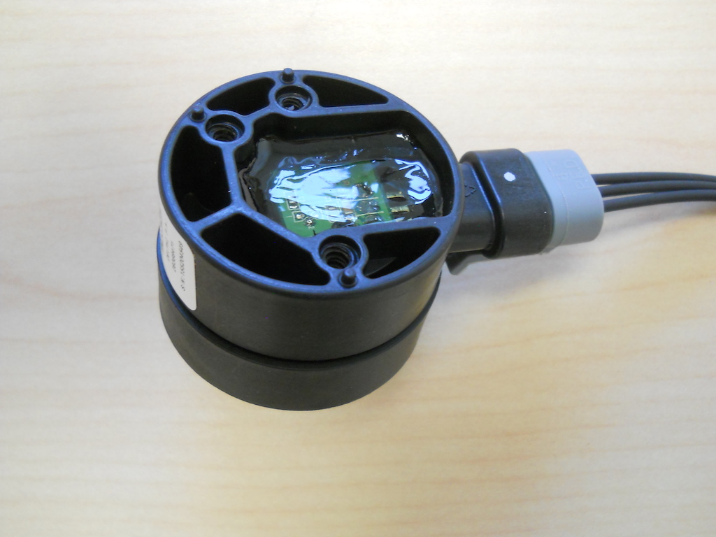
With 4 of these sensors in hand, I set about confirming their physical and electrical characteristics. They are Hall effect devices, not resistive potentiometers, so it is necessary to provide them with a reference voltage and to measure output voltage, rather than simply measure resistance. I used three AA batteries in series to provide a stable reference voltage and measured the output voltage at a variety of rotation angles.

The Motec document conveniently identified the pin functions for the sensor. Rotation angles were measured by applying a calibrated scale to the sensor as a reference.

I measured the following ranges from the lever arm supplied with this sensor. Motec uses a different arm configuration, so their datum is different.

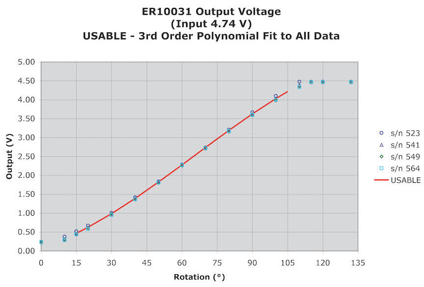
The electrical range and useful range have been extracted from the output data as shown in the following graph. The output is distinctly non-linear with respect to rotation angle (more on that later). I have defined the useful range as 15° - 105° because the output for all 4 sensors is reasonably consistent for all sensors over that range. The output values follow an S curve that I have approximated by a third order polynomial by using Excel to fit a trend line to the data over the range from 15° - 110°.
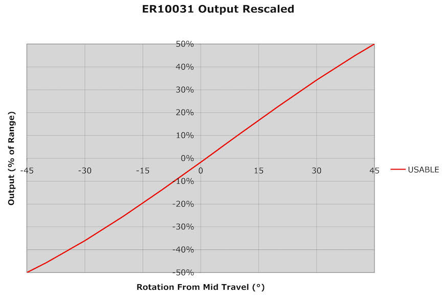
To minimize the installational non-linearity and to maximize the output range, it makes sense to orient the sensor arm useful range to operate at ±45° from horizontal. Referring to the output voltage as a percentage of usable over that range also simplifies the discussion. I have rescaled the output of the ER10031 accordingly below:
One of the perceived shortcomings of a rotary sensor is the inherent non-linear relationship between the vertical height of the sensor arm and the rotation angle. Assuming the sensor is a linear rotary potentiometer, the sensor output will be linear with respect to rotation angle but non-linear with respect to sensor arm (and ride) height.
So here is where things get interesting. Assume we have a sensor that has a linear output with respect to ride height over a range of heights of ±0.5 (units). We can map that output against the rotation of an arm that rotates ±45°. That arm has a length of 0.5 x SIN 45° = 0.7071 to make that work out. At any given height, the arm angle is ASIN(h/0.7071). Tabulating a few values:
Height Angle
0.5 45.0
0.4 34.5
0.3 25.1
0.2 16.4
0.1 8.1
0 0.0
-0.1 -8.1
-0.2 -16.4
-0.3 -25.1
-0.4 -34.5
-0.5 -45.0
Plotting these against the ER10031 output with respect to arm rotation angle, we see a very good match.

In other words, the non-linearity built into the ER100xx sensors has been designed to compensate for the inherently non-linear relationship between rotation angle and height change when using a rotary sensor. Very clever design.
Next task figure out how to mount the sensors.