For those that are not familiar with the upper shock mounting point, here is a look at the hole where it mounts in the body, looking from below. The pressed in steel insert fully supports the lower half of the upper shock mount.
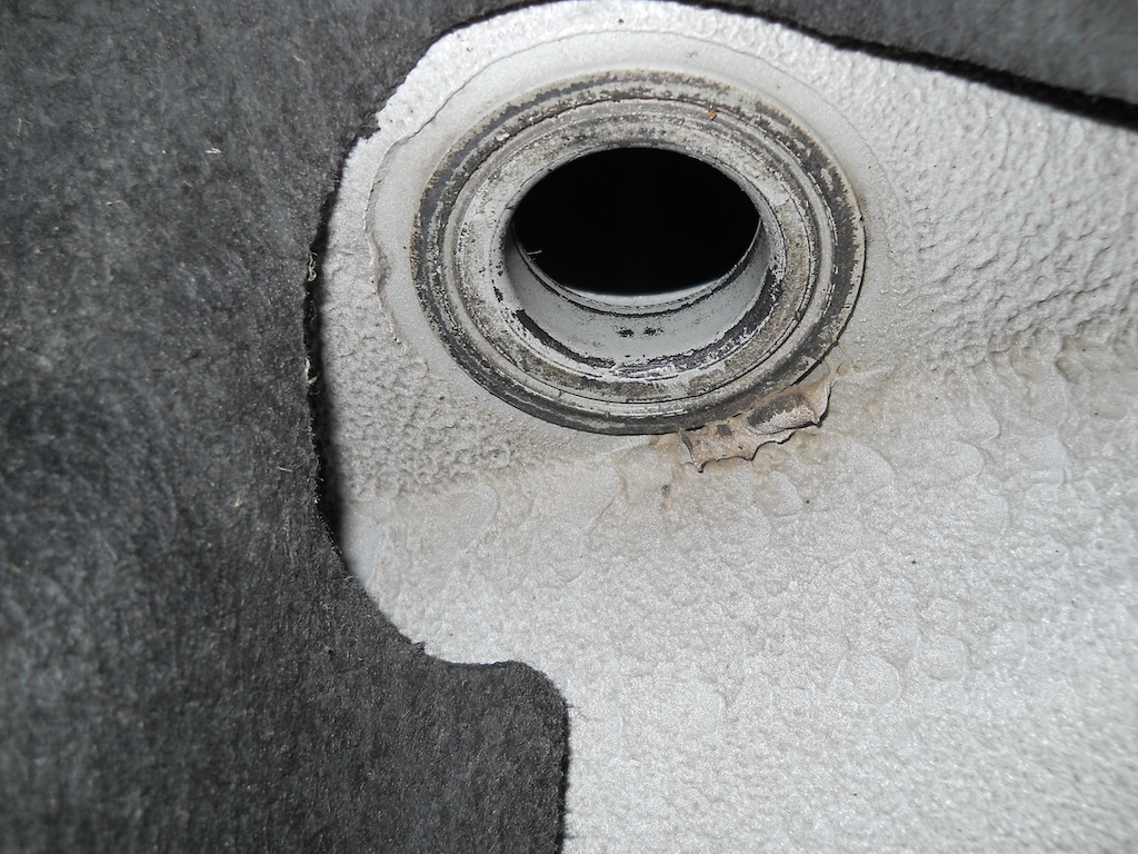
The same mounting point looking from above shows that the support area for the top half of the mount is reduced by a counterbore and large countersink.

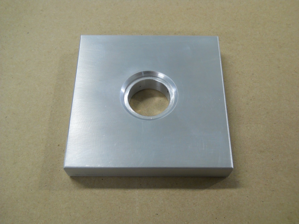
For the bench test of the upper shock mounts to be representative the test fixture needs to have this feature. My fixture block has been adjusted for bore diameter and thickness to compensate for the dust boot that is normally installed on the lower mount. I did not want to test with this boot in place because it obscures what is happening.
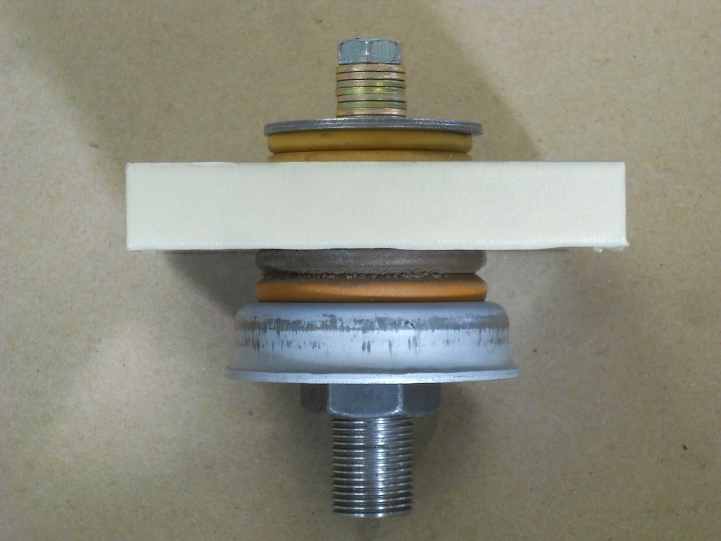
Here is the test fixture assembled finger tight with the OE microcellular urethane mounts at their uncompressed thickness. The orientation is as installed in the vehicle.

Here the assembly has been fully torqued showing the urethane mounts compressed to their installed thickness. An internal bushing controls the amount of installed compression. Because the lower half of the mount is fully supported and the upper half is only partially supported, they compress different amounts when installed. The top mount loses 38% of its uncompressed thickness, while the lower mount loses 20%.
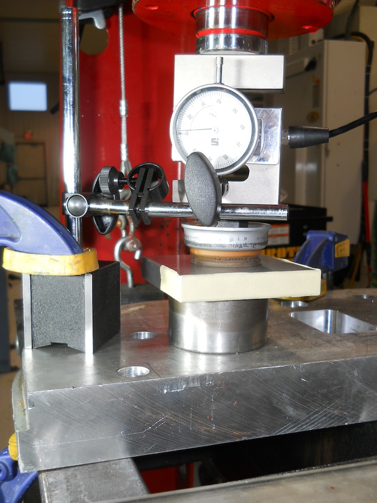
Here is the test setup for the OE mount. Applied force is measured by an electronic load cell and deflection with a dial indicator.
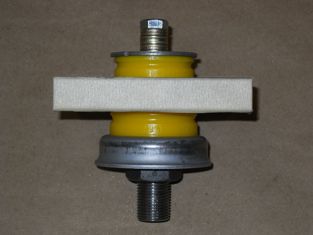
Here is the test fixture assembled finger tight with the Powerflex yellow urethane mounts at their uncompressed thickness.
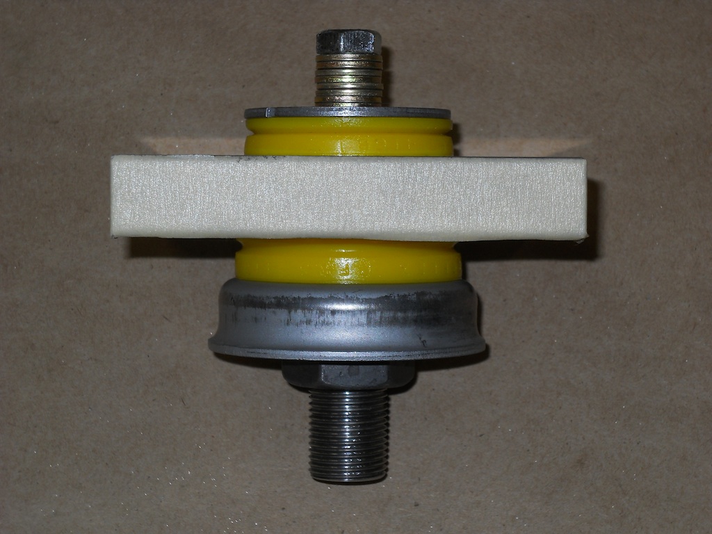
Here the assembly has been fully torqued showing the Powerflex mounts compressed to their installed thickness. The top mount loses 28% of its uncompressed thickness, while the lower mount loses 19%.
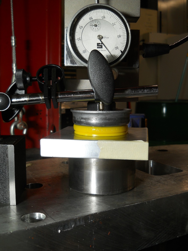
Here is the test setup for the Powerflex mount. This is at maximum applied force of approximately 1800 lbs.
Load vs Deflection was plotted for each of the mounts and a linear regression line was fitted to give the stiffness. Below the stiffness of the OE lower shock mount, OE upper shock mount and Powerflex Yellow upper shock mount are shown in Imperial units. As can be seen, the Powerflex mount is comparable in stiffness to the OE lower mount and is approximately 7 times stiffer than the OE upper mount.

Same again in Metric units:
