This weekend, actually finishing something seemed like a worthy goal. The rear was basically ready to button up so I headed back there again with the idea of getting the trunk liner fitted and installed and the rear suspension aligned.
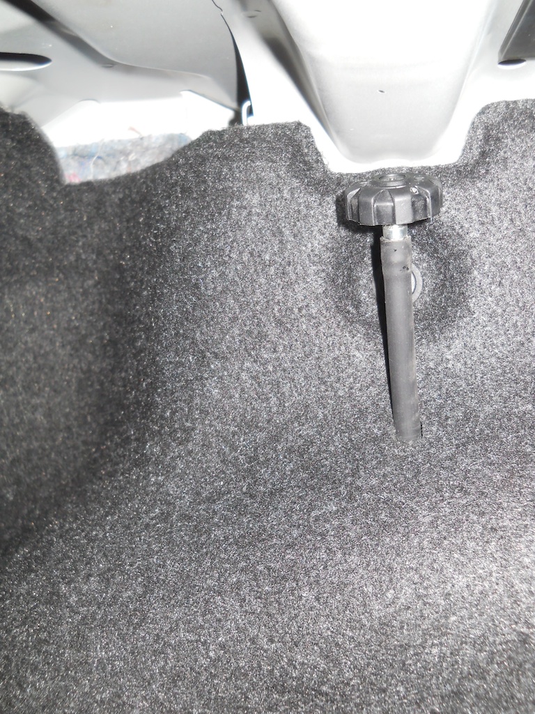
My decision to alter the rear shock top mounts meant that the adjuster knobs would now sit correspondingly higher unless I shortened the adjusters. A trial fit showed that without shortening they would rattle incessantly against the body. The adjusters are made from speedometer cable so the end needs a light touch with a TIG torch to stop it from fraying where cut, but otherwise this modification was uneventful.

The trunk liners need to have a hole put in them for the adjuster cable to pass through. Ohlins provides detailed measurements for locating the hole, but they apply only to the 3-series. On the 1-series, the hole should be directly in below the existing fastener hole, not 20 mm aft as shown in the instructions. I made the hole with a 10 mm gasket punch, and elongated it vertically to 14 mm.

This location and hole size worked perfectly.
Installing the trunk liner is much easier if the rear seat side bolsters are removed first. In fact, it is probably impossible to feed the adjuster through the liner without doing so. Removing the bolsters takes a firm pull at the top of the bolster to disconnect the large white plastic clip that attaches it to the body.

A second vertical pin feature in the bolster also holds it in place.

The white plastic clip can be removed from the body by depressing a trigger inside the clip. The clip is then reinstalled on the bolster before pushing the bolster back into place. Done correctly the process is very easy.

Next on the list is aligning and torqueing the rear suspension. To that end, I made myself a checklist of fasteners and torques to ensure that I didnt miss anything. I also reconfirmed my desired alignment settings, built some decent shims to level my floor for weighing and aligning. Then I embarked on the steep learning curve
This is the process I have figured out for aligning the rear, with my targets in brackets:
1) Set the ride height.
2) Torque all suspension arm bolts with the suspension at ride height.
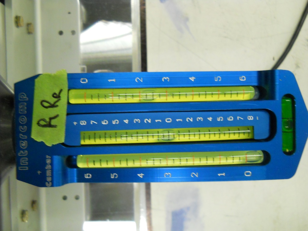
3) Set the camber exactly (-2.25° ± .06°) with the toe close and then torque the camber eccentric bolt.
4) Set the toe exactly (+0.05° ± 0.03°) and then torque the toe link eccentric bolt.
5) Confirm all settings
Because static load on the suspension tends to increase negative camber and increase toe out it is important that the eccentric bolt cams engage on the face that resists these tendencies, otherwise the settings will tend to creep when torqueing the nuts. Thus the camber target should be approached in the direction of decreasing negative camber and the toe target should be approached in the direction of increasing toe in.

It is important too that your target values are clearly known, and just as important, a realistic tolerance should be applied to those values given the technology at hand. I would say that I got the results I wanted using the hub stands I built, but doing so took a large effort. In particular, working under the car at only jack stand height does not provide much room to swing a torque wrench and those eccentric bolts are very easy to inadvertently turn while torqueing their nuts. Another 12 inches of ground clearance would have been very welcome. Removing the axle-back exhaust would make things simpler too, but I didnt do that.
I will give some more details on the hub plates when I align the front suspension.
Here is my fastener checklist, which I initial as each fastener is torqued. The torque values generally come from the Bentley 3-Series Service Manual.

The only fasteners not yet torqued at the rear are the anti-roll bar end links. I am leaving these disconnected until I have completed the corner balancing of the fully aligned car.