I installed both the front and rear suspensions set provisionally (but precisely) at my best estimate of the correct spring perch settings. Putting the car down on its wheels revealed that my rear ride height was 7 mm lower than my target of 334 mm, so I adjusted the rear spring perches down by 4 mm (7 mm times the spring motion ratio) and the rear ride height is now correct. The front ride height is about 2 mm low, which is fine for now.
I have provisionally corner weighed the car with these ride heights. I say provisionally because the front calipers and a few other parts were missing from the weighing, although I did ballast the driver’s seat with 170 lbs. The weighing is not intended to be definitive, just a check of the general state of balance. The results are very satisfying with the cross balance within 0.3% without making any adjustments.


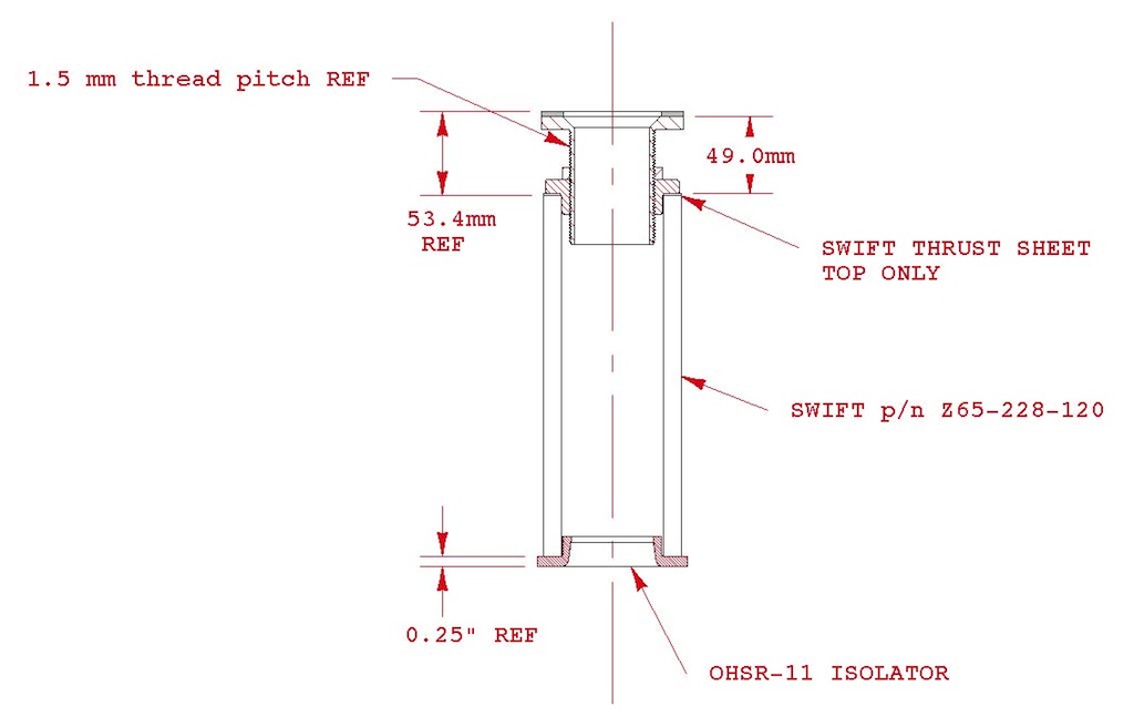
Now that the rear spring height is set, I have looked back at some of the earlier data that relied on assumptions and pinned it down with actual numbers. Specifically I have correlated ride height precisely to centre line spring length at the final rear spring perch setting. The following drawing pins down the spring configuration precisely.

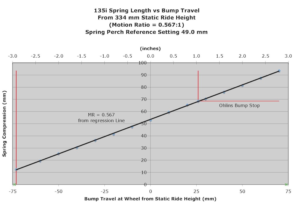
In Part 1, I looked at an abstract spring compression vs bump travel that did not fully reflect all the elements in the spring load path. I now adjust this to reflect the actual spring compression vs bump travel for my final spring setting and ride height. This has no effect on the calculated motion ratio, it just shifts graph vertically and allows me to define the vertical axis as true spring compression. As can be seen, at full droop the spring is positively preloaded (although this would be reduced if the ride height were lowered).

It is worth noting that the maximum practical spring compression (about 95 mm) is less than the maximum usable stroke defined by Swift for this specific spring (4 in = 102 mm). Maximum spring compression is established by when the tire hits the wheel well. This is wheel, tire and camber dependent.
In Part 4, my final graph attempted to look at the non-linearity in the rear spring resolved at the wheel, normalized with bump travel. All is not well with that graph for a couple of reasons. First, the spring perch setting at which the data was taken did not result in the predicted ride height (7 mm error) and second, I transcribed a couple of digits in my spreadsheet. I am not going to try and fix it. Instead, I have measured the wheel load as a function of bump travel for the fully installed suspension (including shock, bump stop and rubber bushing bolts torqued at ride height). The bushings contribute no support at ride height but they increase the spring rate. In Part 3, I measured the support provided by the shock to be about 37 lbs at the shock, so about 29 lbs at the wheel (when multiplied by the shock motion ratio of 0.792). The bump stop provides no support in the range that I measured. The following graph shows the comparison of the spring only wheel reaction (assuming pure axial compression) and the measured wheel reaction. Wheel loads were measured with the shock set at full soft and with time for the fluid pressure to equalize across the shock piston.

The additional stiffness of the full installation must come from the rubber suspension arm bushings. There are 8 of these in total acting on each side (assuming all stock components – the M3 arms will reduce that by 1 and a ball jointed toe arm will remove another 2). The theoretical wheel rate of the spring acting alone is 220 lb/in while the measured rate for the complete suspension is 261 lb/in. This implies that the rubber bushing, which act in parallel with the shock and suspension spring, have a collective wheel rate of 41 lb/in. The load and deflection were measured while loading the suspension and then while unloading to check for hysteresis, which would indicate suspension binding. While some hysteresis is present (and expected), it is not excessive.
We can combine the 261 lb/in wheel reaction due to the spring with that due to the bump stop to get the total wheel reaction throughout the full range of rear suspension travel. As can be seen this suspension can easily support 100% lateral load transfer.

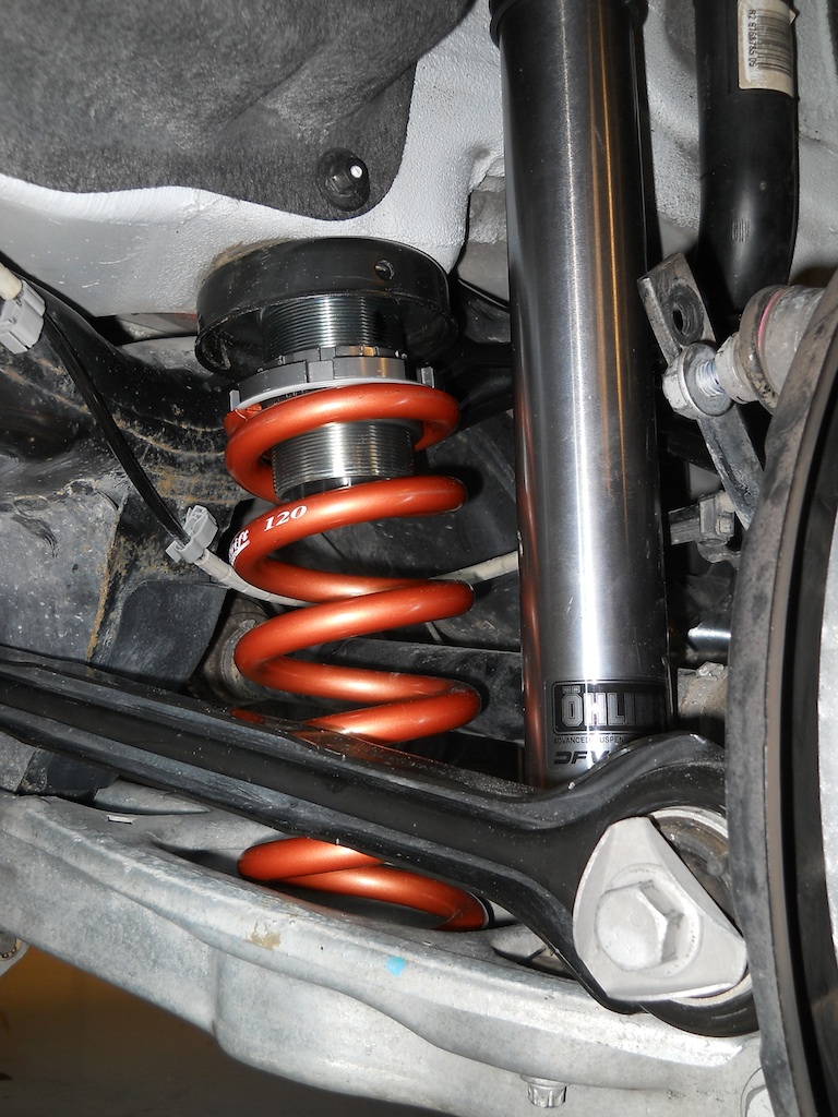
Before I leave the rear suspension for a bit, I want to revise my opinion regarding the orientation of the rear spring. Putting the logo facing aft puts the spring ends at the back of the car where the rocking motion of the spring will have the least tendency to cause them to gouge into the lower spring pad.

In the next installment it will be time to start looking at the front suspension details,