Our rear suspensions consist of virtual upper and lower A-arms plus a toe link. Each virtual A-arm consists of a pair of struts, for a total of 5 strut elements. Although a rear suspension does not steer, it still has a kingpin axis about which it would steer if unrestrained by the toe link. Accordingly it also has a kingpin inclination angle (KPI), a caster angle, a scrub radius, mechanical trail and of course camber and toe angles. The following graphics are annotated versions of what SusProg3D presents after solving the geometry.


The rear suspension has negative caster, negative scrub radius and negative mechanical trail. The why behind these design choices is interesting.
In contrast our front suspensions have positive caster (7.3°), positive mechanical trail (24 mm) and negative scrub radius (-11 mm), all of which are typical for front suspensions. Positive caster and trail result in a self-aligning torque about the kingpin axis in response to cornering forces. This is why steering effort increases with increased cornering g and why the steering wheel will tend to center itself if released in a corner. Negative scrub radius results in a toe-in torque about the kingpin axis in response to braking forces. This is a stabilizing influence under braking when combined with the unavoidable compliances in the front suspension. All these characteristics are desirable in a front suspension.
The self-aligning torque present in the front suspension tends to cause the front outside wheel to toe out in response to cornering forces. This torque will act with the compliances in the suspension to actually cause a small toe-out, and is therefore a stabilizing or understeer influence.
In contrast any toe out tendency in a rear suspension is a destabilizing or oversteer influence. Therefore self-aligning torque at the rear, acting with any compliance in the rear suspension is very undesirable. This explains why our cars have negative caster and negative trail in the rear. Both of these factors will result in a toe-in torque about the kingpin axis, which combined with any compliance will result in a stabilizing toe in rear steer reaction to cornering g. Due to a phenomenon called pneumatic trail, the side force generated by a tire does not act at the centre of the contact patch, but acts slightly aft of that point, and therefore is a toe-out or destabilizing influence. By taking all these factors into account, BMW has ensured that the rear compliance steer response will be toe-in (stable, understeer) and that the magnitude of the aligning torque at the rear is low and thus easily handled by the original toe link and its rubber bushings.
Negative scrub radius is stabilizing (toe-in influence) under braking at the rear, but destabilizing (toe-out influence) under acceleration so a bit is desirable for braking, but not so much as to be problematic under acceleration.
Negative caster is typical in rear suspensions and is readily apparent when looking at cars with strut rear suspensions. Internet chatter on this subject almost universally misses the mark as to why. Quite simply, it is to reduce loads on the toe arm and to ensure that any compliance rear steer is toe in and stabilizing in response to cornering g.
Incidentally, a multi-link suspension cannot be solved graphically. The virtual upper and lower king pin points are located at intersection of the upper and lower pairs of arms respectively when viewed along the king pin axis. But the king pin axis is defined by the virtual upper and lower king pin points. See the chicken and egg problem? You can only see the solution once you know the solution. Luckily SusProg3D solves the problem easily.
The main observations from the SusProg3D data for the rear suspension can be summarized as follows:
1) Scrub radius is approximately -44 mm (but can be adjusted to close to zero by insetting the lower ball joints in the upright).
2) Trail is approximately -40 mm at ride height.
3) Caster is approximately -8.3° at ride height.
4) Bump steer varies from approximately 0.1° toe in at full bump to 0.3° toe out at full droop. Slight toe in under bump is a stabilizing influence.
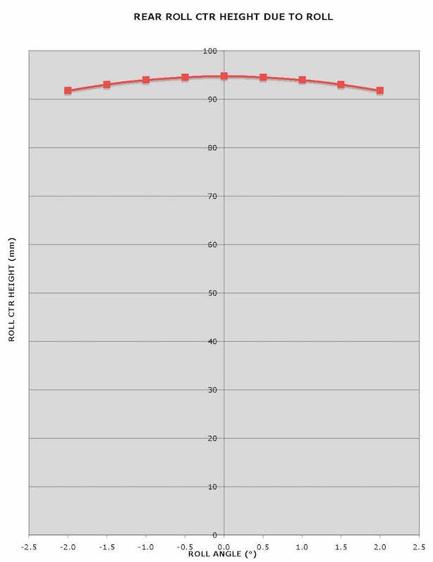
5) Roll center height as a function of roll angle is shown below. Unlike the front suspension, roll angle has little effect on roll center height.
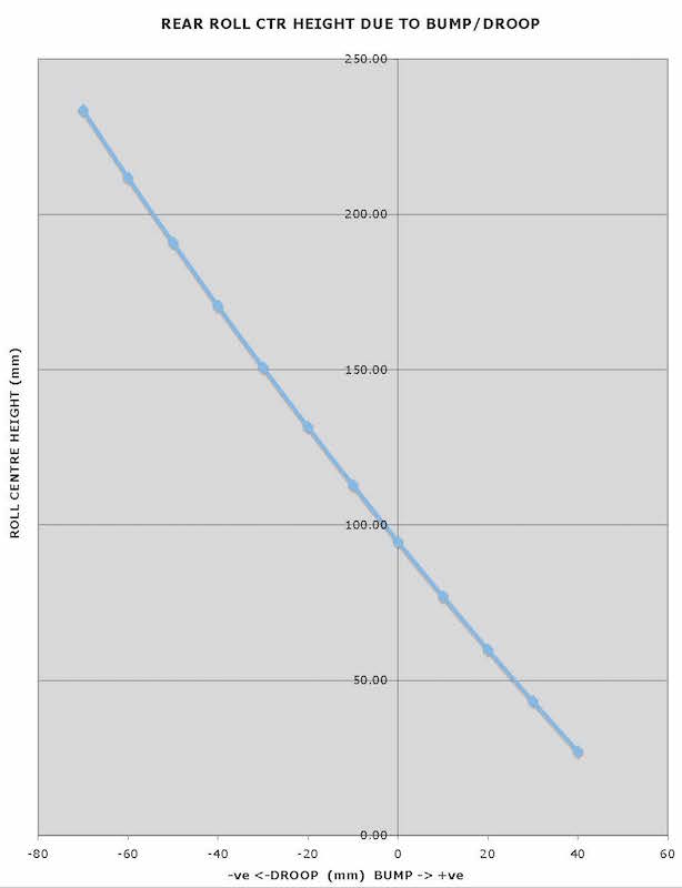
6) Roll centre height moves proportional to ride height.
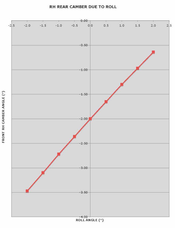
7) Rear camber gain with roll is greater than the roll angle, ensuring that the outside rear tire maintains a negative camber angle relative to the road.
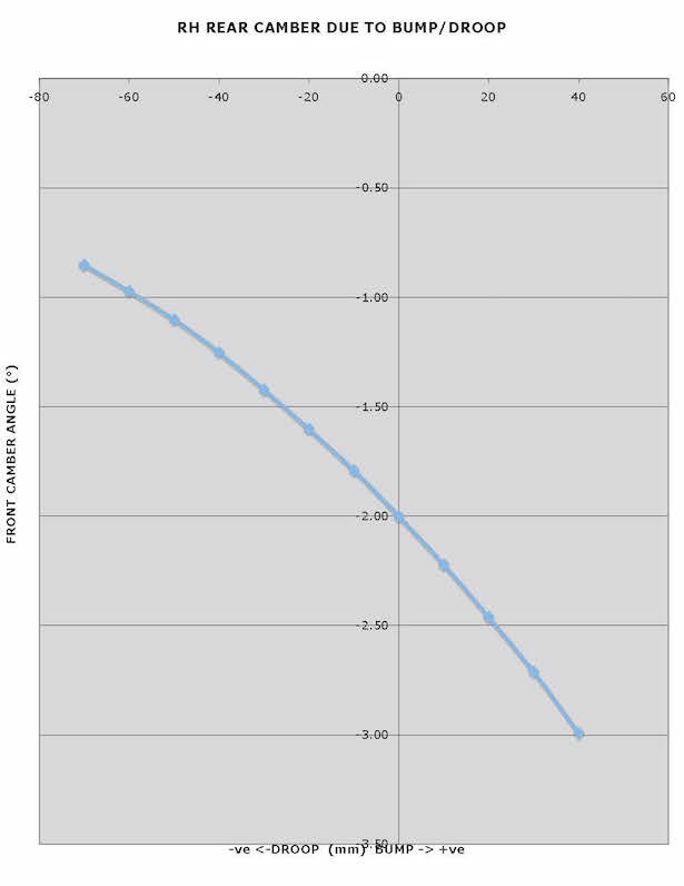
8) Rear camber gain accelerates with bump, unlike the less favourable response of a strut suspension.