Time to look at the front suspension. I am starting with the following constraints, selected by me:
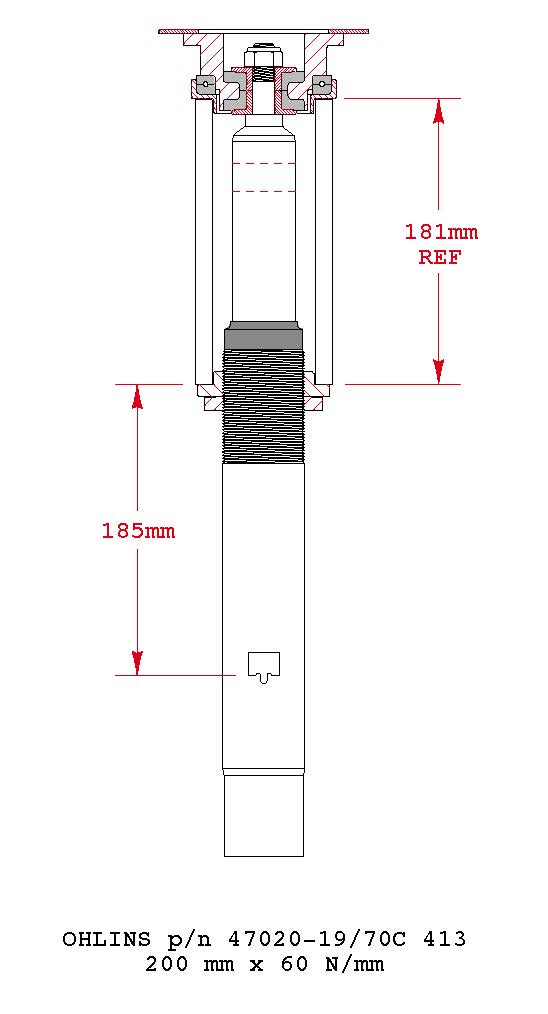
- Ohlins 200 mm x 60 N/mm spring
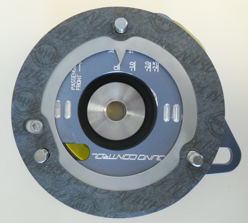
- Ground Control Street Camber Plates
- Wheel Center Ride Height = 326 mm
The choice of a 60 N/mm spring is based on three things: 1) consensus on the forum that this is a good rate, 2) the fact that this spring comes with the Ohlins kit (and my testing shows it to be of good quality), and 3) the observation that this spring rate is also specified for the 1M kit (paired with a 120 N/mm rear spring). The hope is that the 200 mm length will work with respect to wheel and tire clearance, but this needs to be verified because the lower spring perch setting is affected by the choice of the Ground Control camber plates.
Ground Control street plates were chosen based on the fact that I had them previously installed and I like the idea of a urethane isolated plate for a combined street/track vehicle. I saw no reason to change, although I did need to get the upper race spring perch from GC to replace the OE spring version used previously.

My ride heights are arbitrary and given the raging debates over ride height, I will leave it at that, except to say that form follows function.
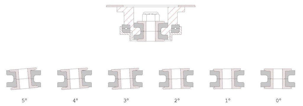
Back to the camber plates. When I first installed the plates, I modified the indicator plate by welding a stainless cap screw in the threaded hole provided by GC to act as a locating peg. They don’t tell you the function of this hole when you buy the plates, but it is perfectly located for a locating peg, which biases the plate location in the direction of maximum camber (in the slotted holes in the strut tower).

Without this locating peg, the indicator plate will float within the range of the slots and repeatable camber settings will not be possible. This little addition really is essential.
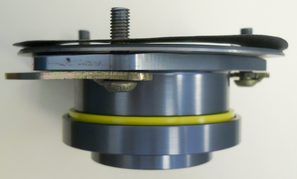
One season of experience with the plates and I discovered that the shoulder bushing and washer that GC provide to contain the urethane bushings suffer a bit. In particular, the washer, which GC artistically adorns with their logo laser cut out of the part, bends in service. Also the urethane tends to extrude itself through the laser cutouts. The bushing as supplied has a countersunk lower hole to suit the OE shock top, which is not suitable for the Ohlins non-tapered top. GC can provide a non-countersunk version, but a couple of other observations prompted me to design my own 2-piece stainless steel bushings. 1) the GC parts were corroded after one year of summer use, and 2) the stack up height would prevent the top nut from being “in safety” (1.5 threads showing through the nylock nut), even with a reduced height nut.
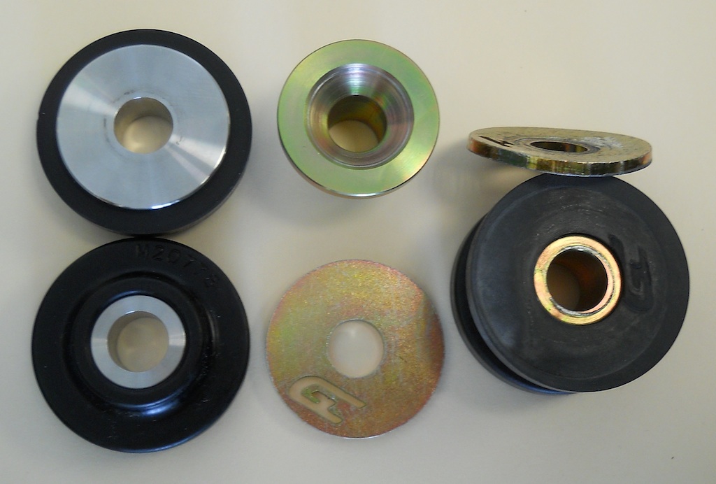
My bushing design also eliminates a sharp edge interface with the urethane because while I am at it, why not.
While I had the plates apart, I replaced the urethane bushings and the steer bearings. The steer bearings are really nice, full spring diameter, units taken from BMW p/n 31-33-1-090-612, so they can be replaced without going back to GC. When you buy them from BMW they come with a metal housing that can simply be removed and discarded. These wear items should be replaced whenever the plates are apart.
The geometry of the camber plates, the length and spring rate of the spring, and the desired ride height establish where the lower spring perch must be located. If you know the front corner weight, the front unsprung weight, the front motion ratio, the free spring length, the spring rate, and all the front geometry you can calculate the spring perch setting exactly. I know most of that, save for some of the fine points of the geometry, so my first try got me to within 2 mm of my desired ride height. A single adjustment got me right on.
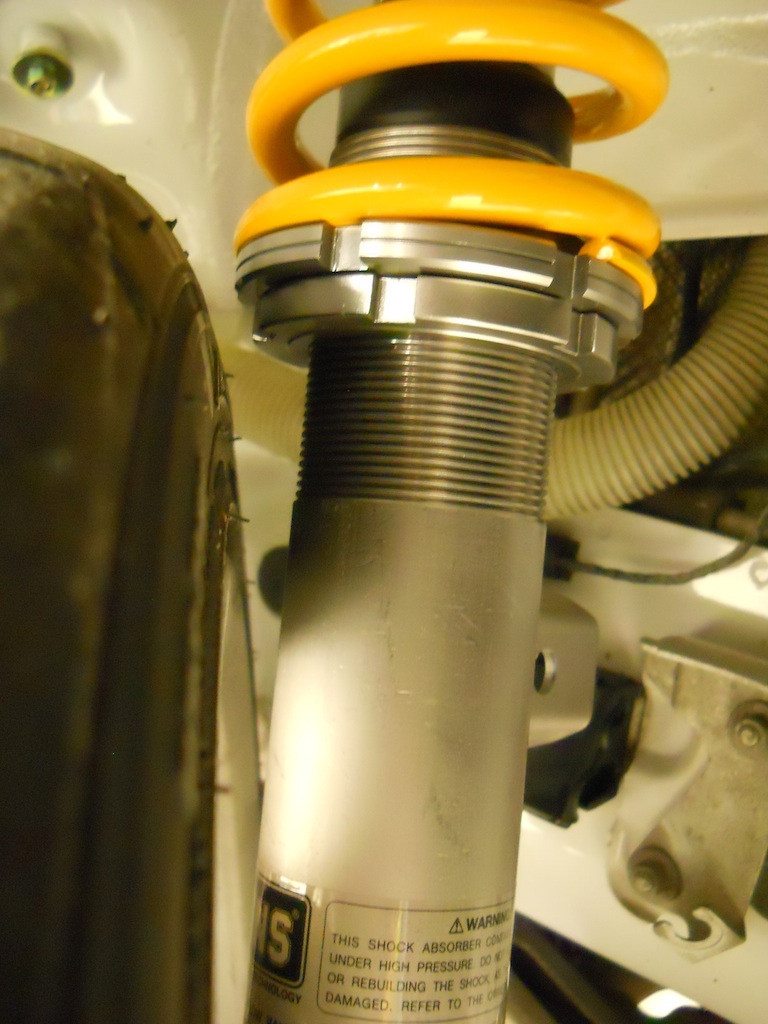
My point really is this – the required spring perch height is much different than what Ohlins recommends in their instructions (for use on a 3-series with OE top mounts). The location recommended by Ohlins would be a disaster with respect to wheel and tire clearance on the 1-series. With my higher spring perch location I have tire clearance (just) with my 225 tires on OE 7.5” wheels. I will not have clearance with wider wheels and tires. Shorter front springs are in my future, but for now I will proceed with the Ohlins front springs. This is an example of the devil being in the details, but by fully understanding this installation I will be able to make an informed choice of a shorter front spring when I move to wider wheels.
One of my original goals had been to use Swift thrust sheets on all springs. At the back it became apparent that they were only practical on the top of the spring. At the front, they are not necessary because the GC steer bearing provide for unrestricted torsion of the spring.
My front setup drawing defines the spring perch location from shock feature that locates the shock body in the steering knuckle. This is the most logical datum as it is directly tied to ride height.
I have previously looked at the bump steer behavior and camber gain at the rear suspension so wanted to do the same at the front.
For bump steer, I wanted to look at the effect of camber changes on toe (so I would know what the toe change would be if I made a camber only change at the track). Also, toe changes will have a small but perhaps measurable effect on bump steer. Caster changes have a much more pronounced effect on bump steer, but my plates don’t permit caster changes. I suggest that anyone with adjustable caster adjust their caster to minimize bump steer rather than for any other hypothetical benefit. Quite likely this means not deviating much from the stock caster setting.
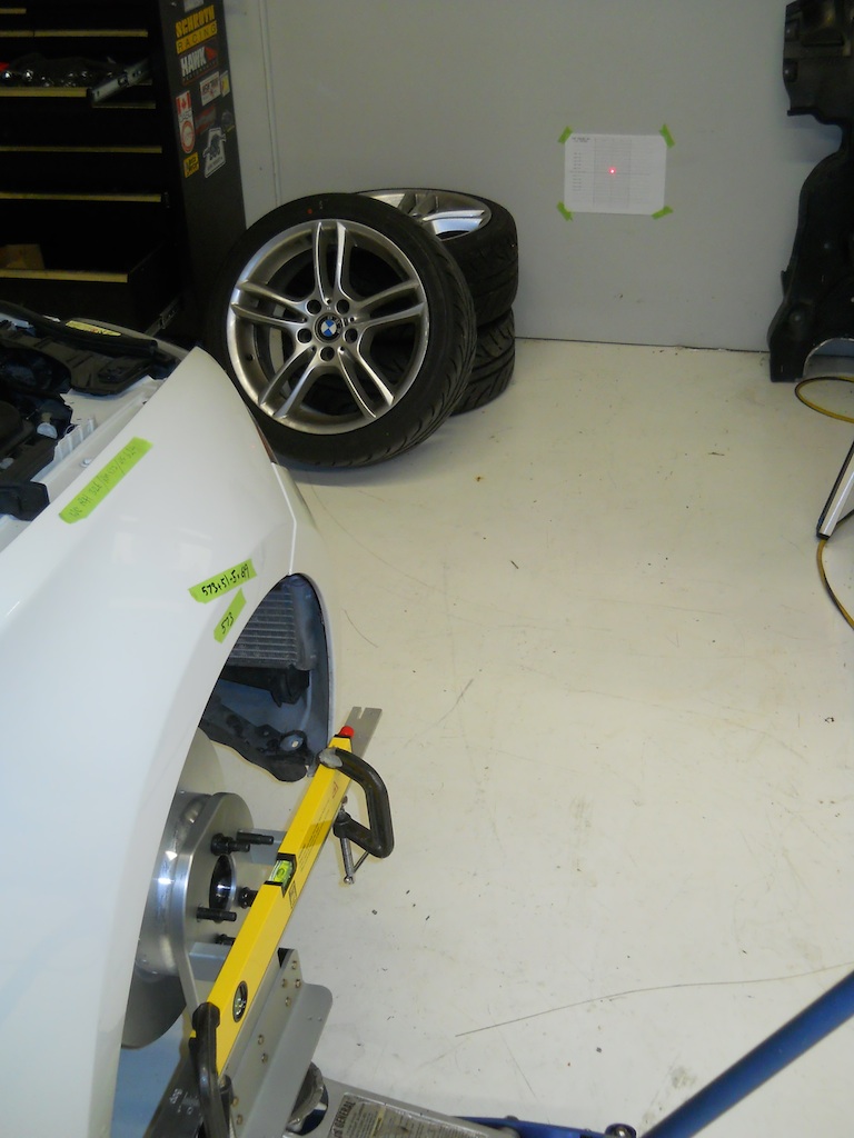
To document the bump steer behavior I used a laser pointer clamped to my hub stands and jacked the wheel through its range of motion (without a spring installed). The laser was projected on a target scaled for the projection distance (in my case 110 inches) to read directly in 0.1° increments. (A handy rule of thumb is the “1 in 60” rule familiar to pilots, that one unit at a distance of 60 units equals 1 degree of course deviation).
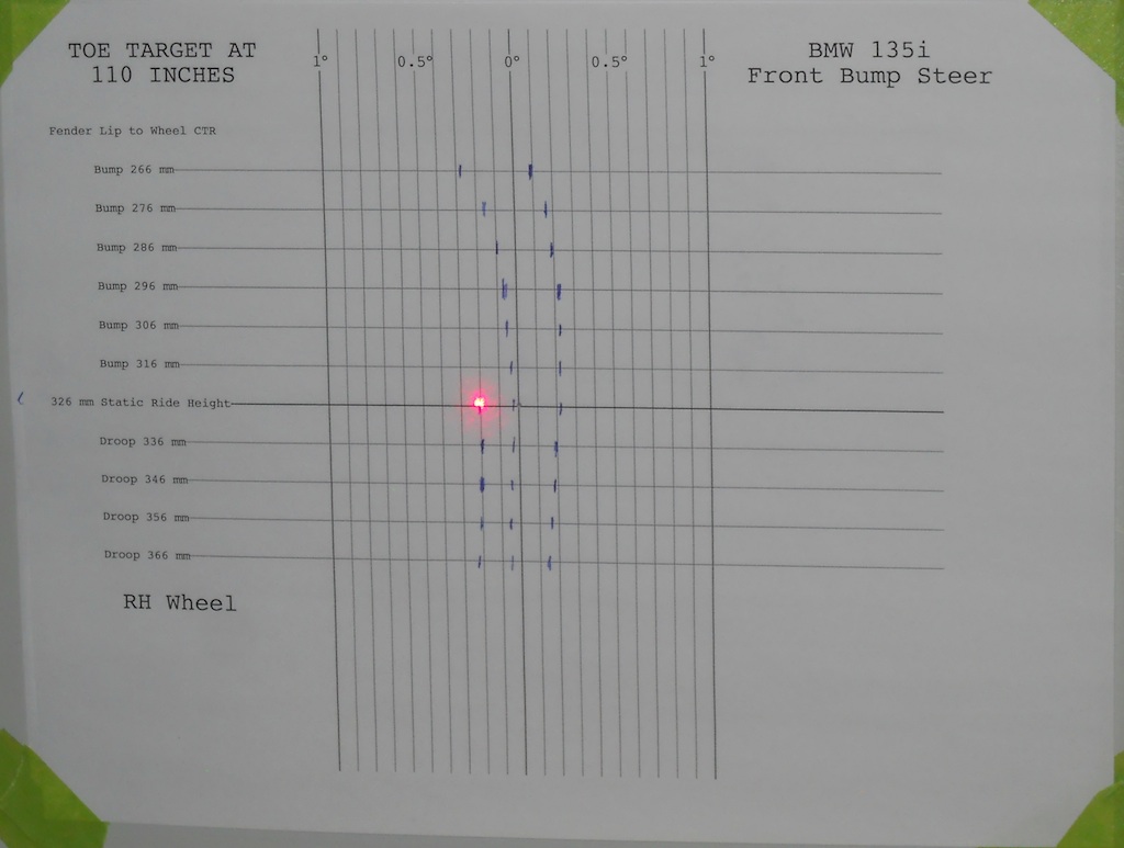
The results show a toe change of approximately 0.2° toe out for each 1° of increased negative camber. The tendency towards toe out with bump at higher camber settings is worthy of consideration as this is generally considered to be an unfavorable characteristic. The results plotted below are effectively for a left front wheel, although they were actually measured on the right front.
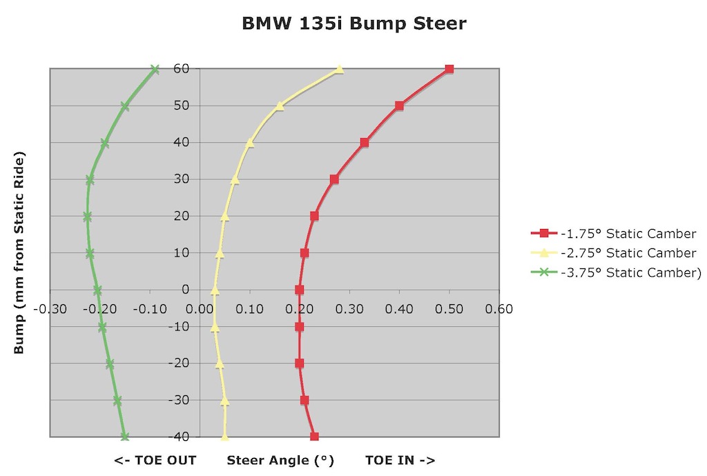
I have previously mentioned rule of thumb with respect to camber thrust:
"For many radial tires, 1.0° of camber produces about the same lateral force as 0.1° of steer (10:1). For bias-ply tires the effect is more pronounced: 1.0° of camber is equivalent to about 0.2° of steer (5:1). From this simple rule of thumb, it can be seen that static negative camber will require toe-out to keep the wheels from fighting each other."
This means that a slightly conservative street alignment with a bit of toe in will become a slightly aggressive track alignment with a bit of toe out with a camber change of -1° at the track.
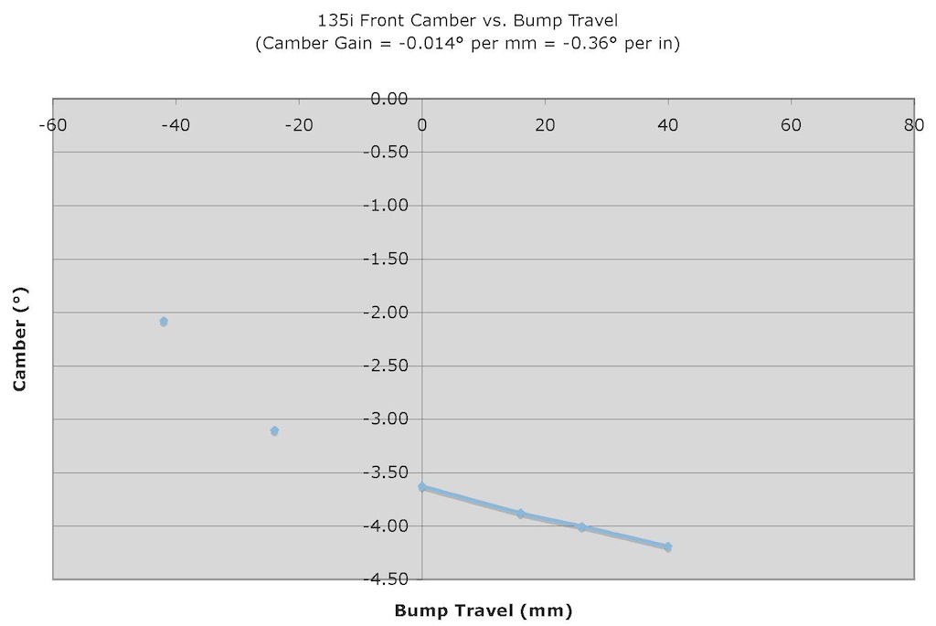
When we looked at camber gain on the rear suspension we discovered that the rear wheel gains -0.02° camber per mm of bump travel (-0.5° camber per inch of bump travel). I presented this in tabular format but it is worth looking at it in graphical form below.
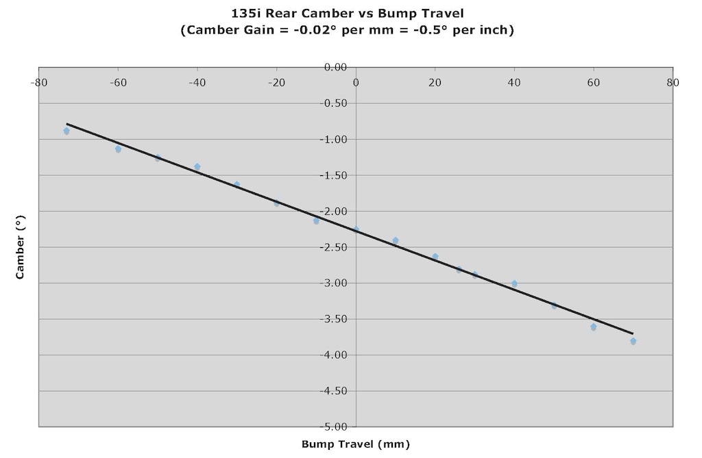
This is a really wonderful characteristic made possible by the sophistication of the rear multi-link suspension. The camber gain on the front suspension is less favorable and inherently non-linear, a characteristic of strut suspensions. In the area of interest (positive bump travel) the camber gain is reasonably linear but will be less favorable at less aggressive static camber settings and at lower static ride heights.