Needing a distraction while waiting for my new front springs I decided to investigate the OE anti-roll bars.
My plan is to start out with the OE anti-roll bars because just the spring change will result in a significant increase in roll stiffness. Also, I have no data to support a decision to change the bars. So while waiting for my new front springs to arrive, I decided to collect some data on the OE bars. That means more measuring and more graphs.
The front bar is extremely easy to remove, so I pulled it out and arranged a test setup using a t-slotted machine bed as a base. A tape measured deflection, a load cell measured load and an engine hoist provided the pull.
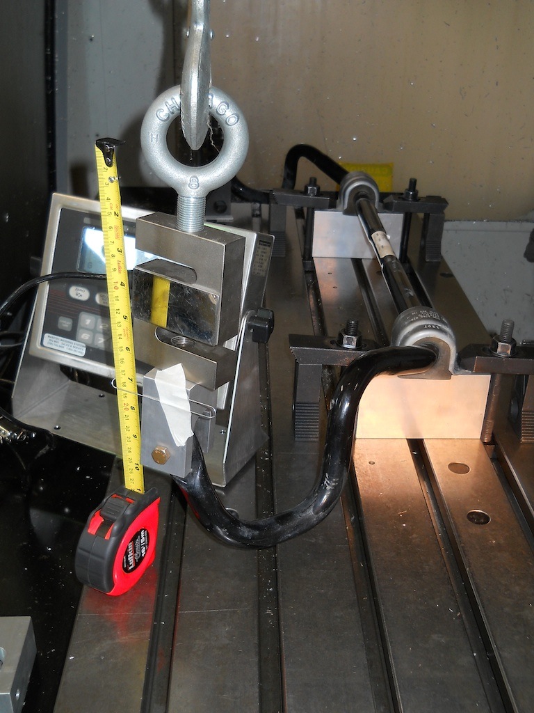
I have tabulated and plotted the data and fitted a regression line to find the bar rate as measured at the end link lug. The other end of the end link attaches to the strut body, so the bar has the same motion ratio as the strut. The effective bar rate at the wheels is the bar rate times the square of the strut motion ratio.
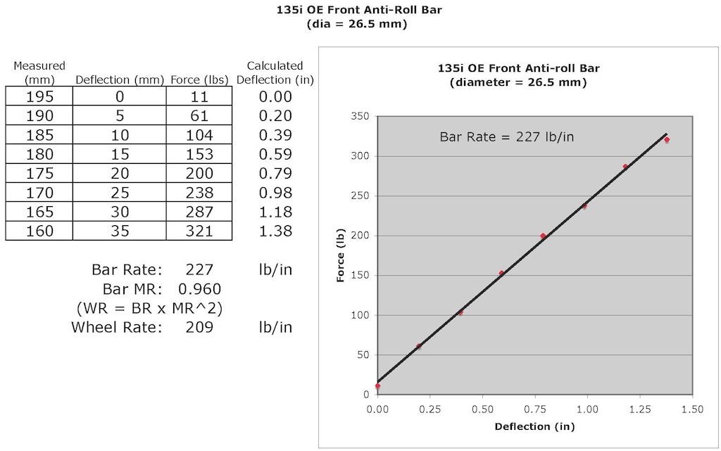
The OE suspension had a reported front spring rate of 120 lb/in, so a wheel rate of approximately 110 lb/in. Thus the front bar contributed twice the roll stiffness that the springs did. With my Ohlins installation the springs contribute a wheel rate of approximately 320 lb/in, which, combined with the OE front bar provides approximately twice the front roll stiffness as OE.
The rear bar is not easy to remove, but is relatively easy to test in place. Whereas most of the front bars deflection is in the tubular torsion spring section of the bar, the rear bar is so flimsy that a significant part of the deflection is due to plain bending of the rear bar. To test the rear bar, the left wheel was blocked while the right end link was disconnected. A series of known weights were hung from the bar with the deflection measured at each test condition.
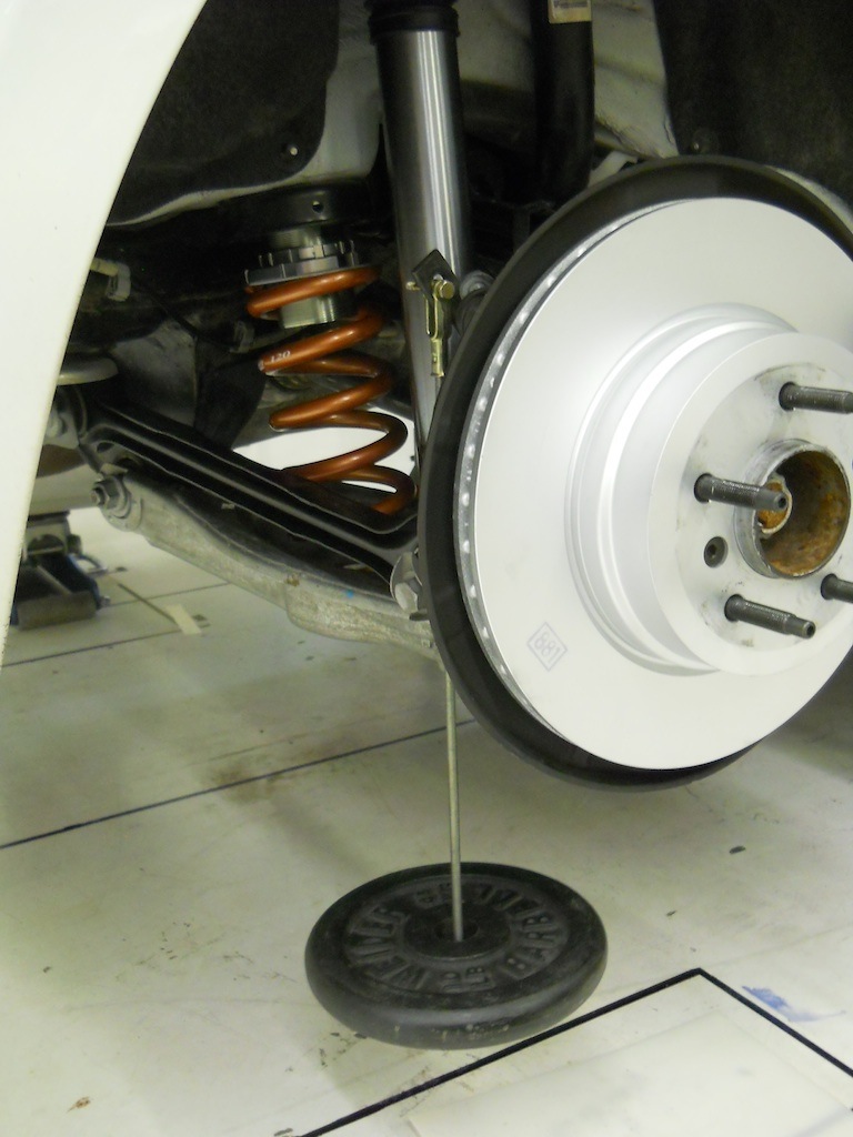
A load of 25 lbs is sufficient to fully exercise the bar as I said, it is very soft! The results are tabulated and plotted below:

The OE suspension had a reported rear spring rate of 350 lb/in, so a wheel rate approximately 150 lb/in (when the bushing effects are accounted for). Thus the rear bar contributed only about 10% of the total rear roll stiffness. With my Ohlins installation the rear wheel rate is approximately 260 lb/in so the bar now contributes only 6% of the total rear roll stiffness and the total rear roll stiffness is now about 1.7 times OE.
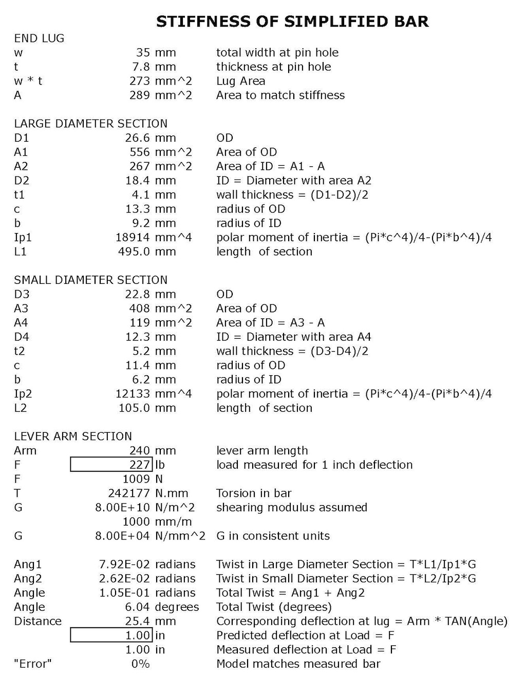
Having an actual front bar stiffness measurement allows me to construct and validate a simple mathematical model of the bar. The usefulness of this is that, if it works, will be to allow me to estimate the stiffness of other bars that I may consider but not have the opportunity to measure. The mathematical model is based on these assumptions:
1) The arms of the bar are much stiffer than the torsion section, so all significant deflection in the bar occurs due to twisting of the torsion section (clearly not valid for the rear bar, but looks reasonable for the front bar).
2) The bar is formed from tubular material with minimal material removal at any section, so every section has approximately the same cross sectional area (possible because the bar is hollow).
As a first approximation, the cross sectional area was assumed to equal the cross section of the bar at the pin holes (assuming no hole was drilled), because the lug is formed by fully flattening the tube end.
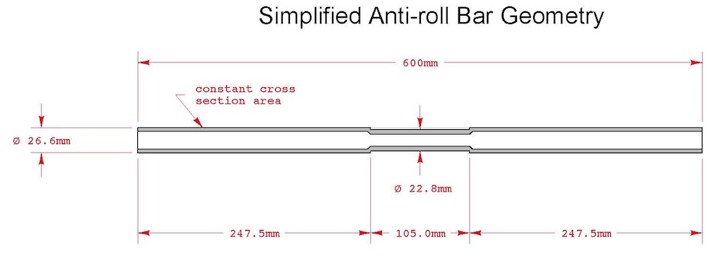
The critical dimensions of the OE front bar are shown below:

The bar can be simplified for analysis purpose as follows by eliminating the tapered sections.
The stiffness of the bar follows from these assumptions and this geometry and is within 4% of the measured stiffness. By adjusting the assumed constant cross sectional area appropriately the model has been made to match the measured data:
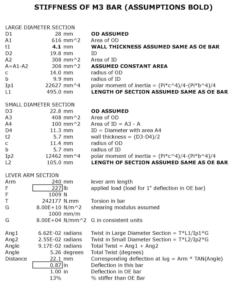
To get an idea as to the stiffness of a 28 mm hollow (M3) bar I have repeated the calculations with several unverified assumptions (I dont have an M3 bar on hand to measure):
Noting that there are several 27 mm solid bars available, I have repeated the calculation for such a solid bar:

SWIFT FRONT SPRINGS
The new Swift front springs arrived, so I wasted no time getting them installed. I outlined the calculated spring perch height required for these springs and you may recall that it resulted in very limited thread engagement on the adjustable lower perch. I decided that 4 full threads was the minimum engagement I would be happy with, so some spring spacers were in order.
I already had some Swift thrust sheets. These consist of an HDPE (plastic) washer toped by a stainless steel washer. The HDPE provides a low friction surface for the stainless washer to rotate on, if necessary to accommodate the spring motions. Conveniently, I had some 0.060 HDPE sheet on hand so I made up some spacers with the same diameter dimensions as the thrust sheet spacers.
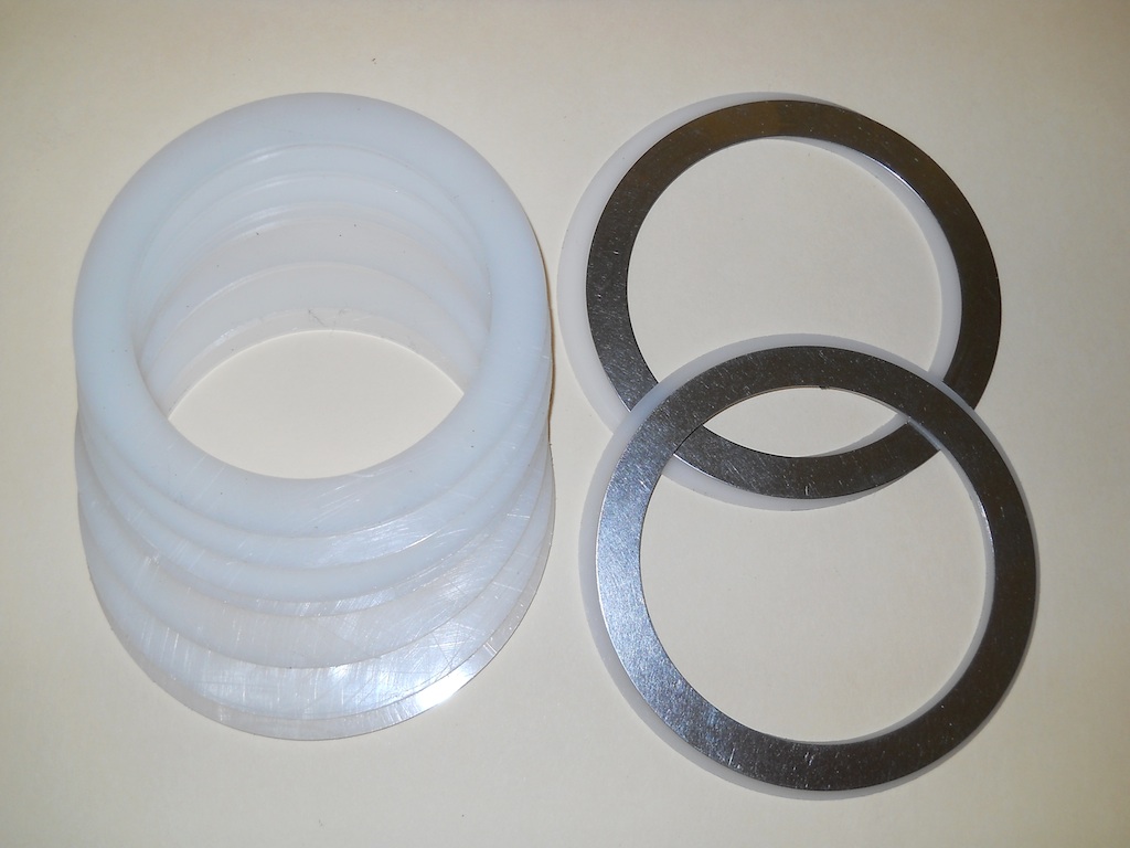
Two of these in addition to the thrust sheets placed my spring perches nicely to maximize tire clearance and satisfy my thread engagement requirement, plus a little margin in case I needed to adjust the perches a bit to achieve cross balance.
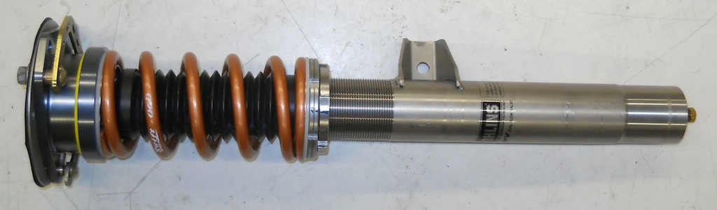
I assembled both struts completely, setting the perch positions with a vernier caliper. To prevent the shock tube from rotating while I tightened the top nut, I used a socket I had modified by machining a hex into its base. That permitted using a regular wrench while holding the strut tube from turning with an Allen key.

FRONT ALIGNMENT AND CORNER BALANCE
I initially set the front camber to -3.25° per my engraved marks. These proved to be a bit out of calibration, plus I noted a bit of left/right asymmetry. My final settings of -3.50° RH and -3.75° LH by the engraved marks resulted in a true camber of -3.25° both sides.
Weighing showed that the RF/LR diagonal was about 1.1% lighter than the LF/RR diagonal. By taking careful notes and noting the change in corner balance and ride height with each adjustment, I achieved acceptable balance in three steps. All that was required was three complete turns (down) on the LR spring perch.
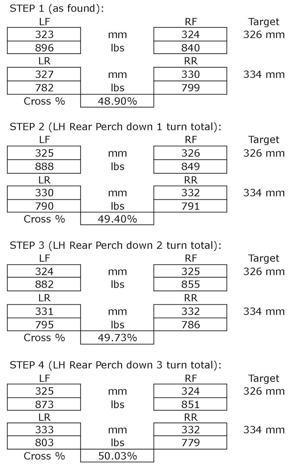
Corner balancing was done with the bars disconnected. Connecting the bars did not change the corner balance significantly. Had it, adjustable end links would have been an appropriate fix to remove any bias from the bars.
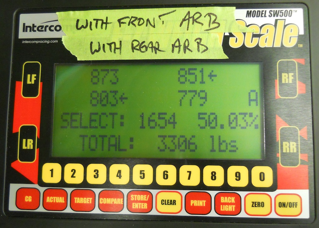
The % figure shown on the scales is the cross balance ((RF+LR)/(LF+RF+LR+RR) as %), which should ideally be 50.0%
At this point I wanted to determine how sensitive the balance was to various factors. Here is what I found:
1) the weight of a full washer fluid bottle changes the cross balance by 0.05%
2) the weight of a 170 lb front passenger or driver changes the cross balance by 0.10% each
3) a mis-leveling of a single scale by 0.08 (2 mm) changes the cross balance by 0.40%
4) cross balance changes with fuel load (because the c.g. of the car is offset to the left, but the c.g. of the fuel is on center).
This does raise the question of just how finely the cross balance hair should be split, because it does vary with occupant and operating fluid loads. I have settled on setting it to within 0.1% of 50% with the expectation that it will remain within 0.5% of 50% under most operating conditions.
Incidentally the car was weighed with 170 lb driver, full fuel, full washer, half fuel, roof racks, on hub stands not wheels, no brake pads, no front calipers, so the weight is not the true empty weight. This car has no sunroof. I will measure a true empty weight on wheels later. Wheels, calipers and pads, being unsprung, dont change the cross balance %.
Final alignment is as follows:

As with the rear, I put together a checklist of torques so that each fastener was torqued correctly and not were inadvertently forgotten.

BRAKE INSTALLATION AND BRAKE PISTON BOOT REPLACEMENT
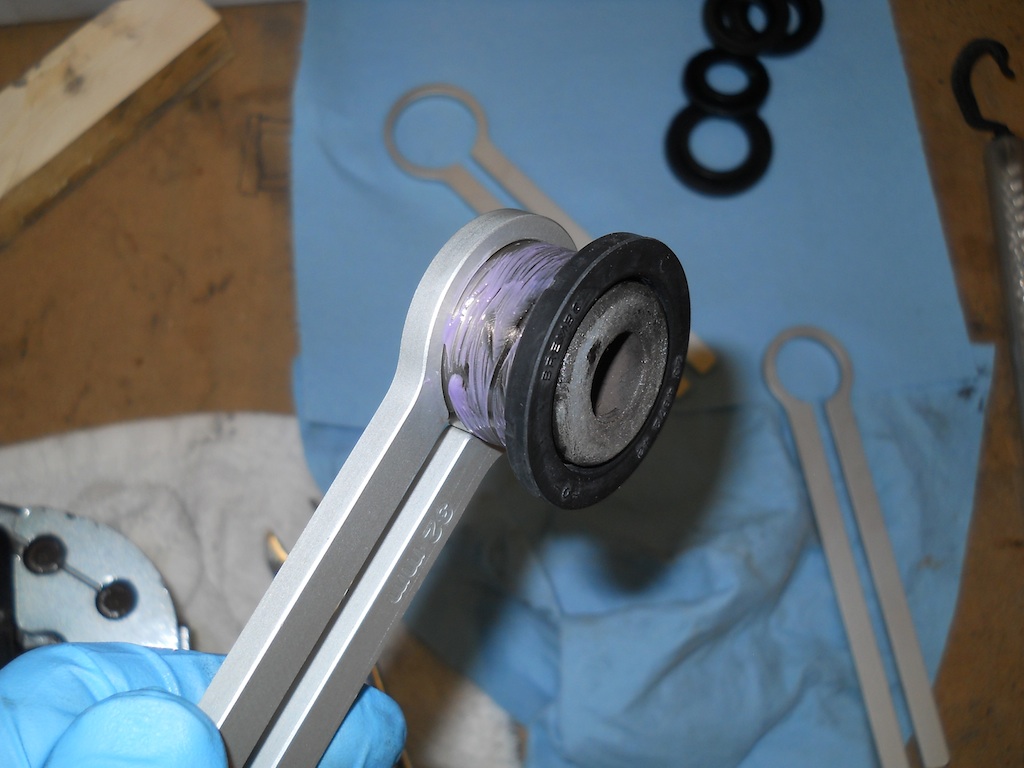
Not strictly part of the Ohlins installation, but a necessary part of the project the front brake calipers needed the dust boots changed on the pistons because they had become charred from previous track days. I had removed the calipers early in the process, which made the replacement of the piston boots much easier. I had also fabricated a set of piston wrenches to assist removing and reinstalling the pistons (4 different sizes are needed to cover both the front and rear calipers). They definitely made the task of removing, cleaning, lubricating and installing the boot easier.
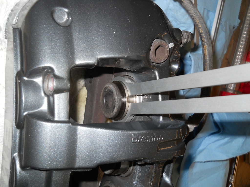
Another simple tool was fabricated from a piece of 2 x 4 lumber, cut to fit in the space normally occupied by the rotor. With this in place, a few careful puffs of compressed air extend the pistons for removal. Without it, inevitably one piston will pop out easily, then the rest wont budge. The correct width of wood allows all pistons to fully extend without any of them becoming unsealed. The wood also provides a cushion so that the fragile phenolic piston nose is not damaged by slamming into its opposite piston.

I lubricate the pistons with a light coat of Permatex Ceramic Brake Lube before installing them. I believe this helps protect them from galling in the cylinder bores. The piston seal keeps the lube away from the fluid, but in any case the lube is brake fluid compatible.
Although I have Hawk DTC track pads, at this moment I am installing OE brake pads, which will be changed before heading to the track.

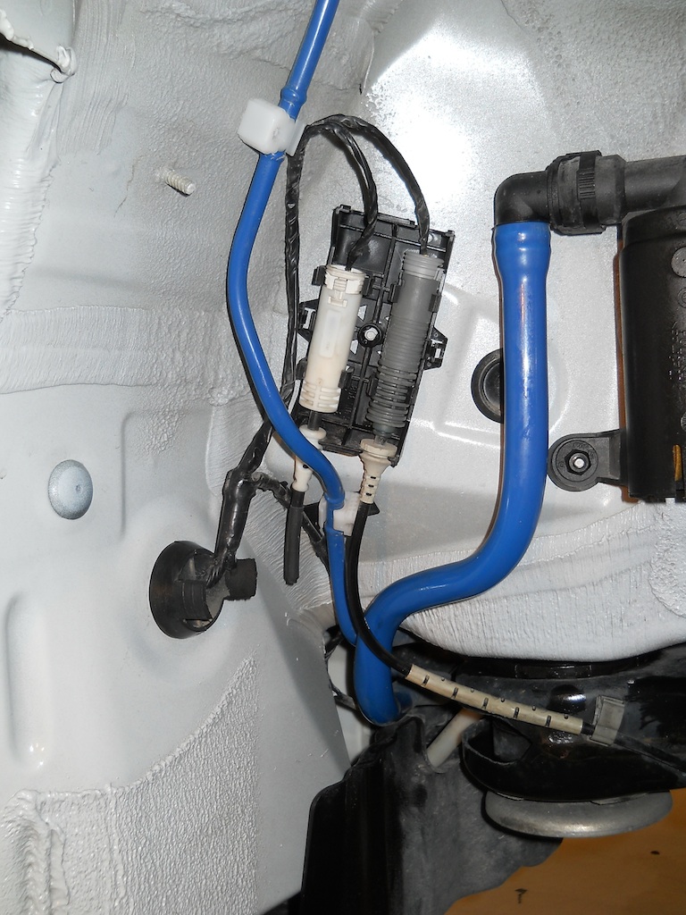
Because I will be switching pads frequently, the brake pad wear sensors are a bother that I want to dispense with. To that end, I have cut off the sensor leads, soldered them together, and sealed the ends with heat-shrink.
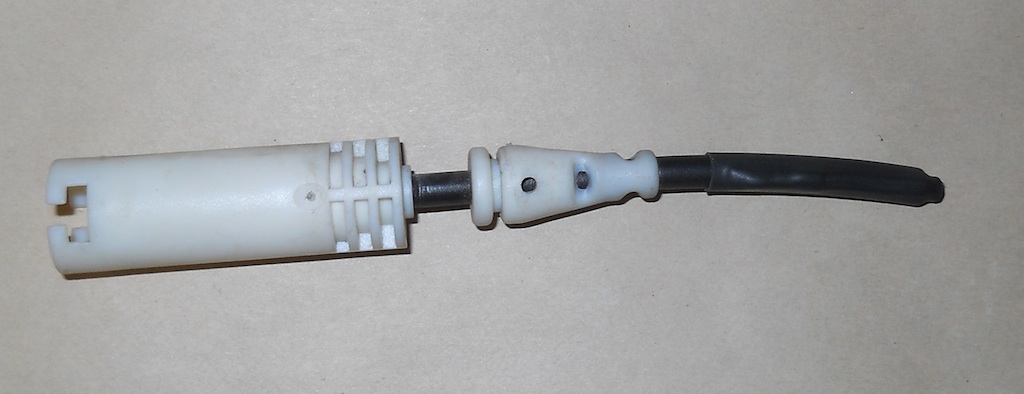
This is the rear lead installed:
Brake bleeding was done with a Motive Pressure Bleeder and Castrol SRF fluid. Bleeding was uneventful
Final tasks:
- Reset the service indicators for the work done (oil change, front and rear brake pads, brake fluid)
- Set dampers per Ohlins recommendation (10 clicks Front, 10 clicks Rear)
- Check tire pressures (36 psi all around) and install wheels
- Install front undertray
- Final inspection for anything amiss
Go for a drive