The OE front strut top mount looks like this in section:
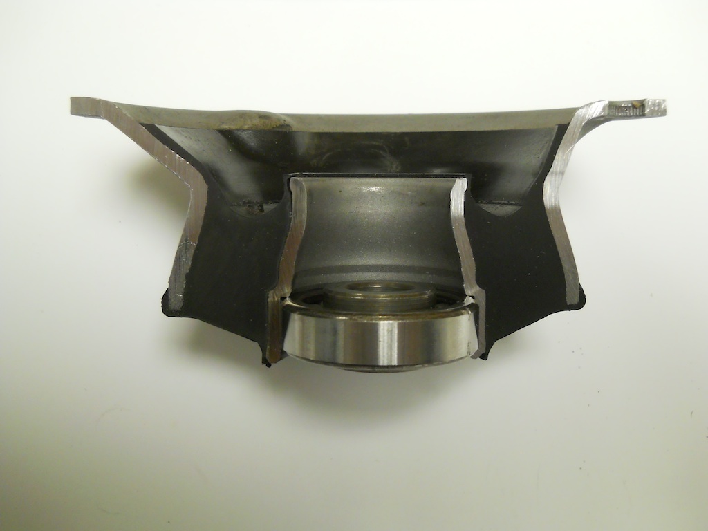
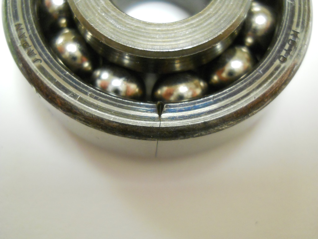
The steer bearing is interesting in that it fully packed with balls. More typically in ball bearings the balls are separated by a cage, and it is the ball separation that permits the bearing to be assembled. Without the cage the balls could migrate to one side and the bearing could fall apart. Along the same line, a fully packed bearing is "impossible" to assemble. A close examination of this bearing shows where the outer race is split to permit it to be expanded to complete the assembly.
Forum member Orb has pointed out that vertical deflection in the top mount is substantial under static loads, and is often not taken into account when considering the stack height in comparison to camber plates. I have been guilty of this omission myself, so I wanted to have a look at exactly how much deflection can be expected. This is actually an easy thing to check when they are installed in a vehicle, but my OE top mounts have been removed and replaced by camber plates, so I rigged up a test fixture, which also allowed me to get an idea of the stiffness characteristics of the mount. Here is the test setup:
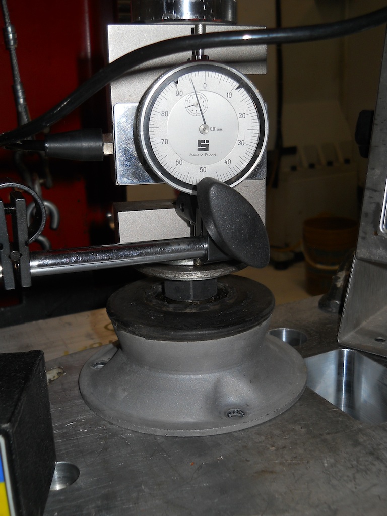
And the results:

I calculate the static load carried by the top mount to be about 850 lbs when unsprung weight is accounted for, hence the static deflection estimate of 0.2 inches or 5 mm.
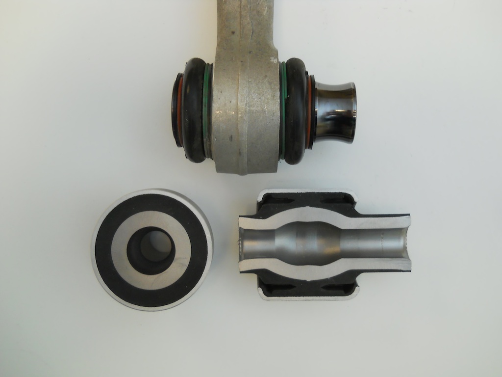
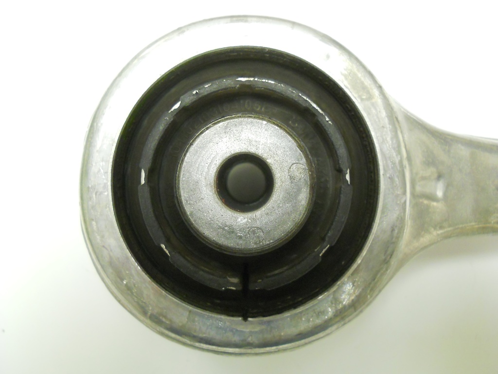
Lateral loads on the suspension are reacted by the wishbone, which has a ball joint at the outboard end and a rubber bushing at the inboard end. In contrast, the M3 wishbone has ball joints at both ends. Any deflection in this bushing as a result of cornering loads will result in a tendency of the corresponding front wheel to steer away from the turn (due to the forward-mounted steering rack), which results in a compliance understeer effect. Accordingly the M3 wishbone is a worthwhile modification for a car that sees the track, although the OE rubber bushing appears to be very stiff (I haven't measured it). The bushing is shown below in horizontal and vertical sections, against an M3 bearing:
"Steady state" aft wheel loads arise from rolling resistance, braking and cornering (the aft component of the tire force due to both steering angle and tire slip angle). In addition transient impact loads from surface irregularities (expansion joints and such) giving rise to NVH issues. To address both considerations the tensions arm reacts these loads in tension as the name would imply. A back of the napkin calculation suggests that apart from severe impact events, the tension loads in this member will be less than about 2000 lbs. The OE tension arm has a ball joint at the outboard end and a large fluid-filled rubber bushing at the inboard end. In the following image, tension loads will shift the inner part of the bushing to the left.
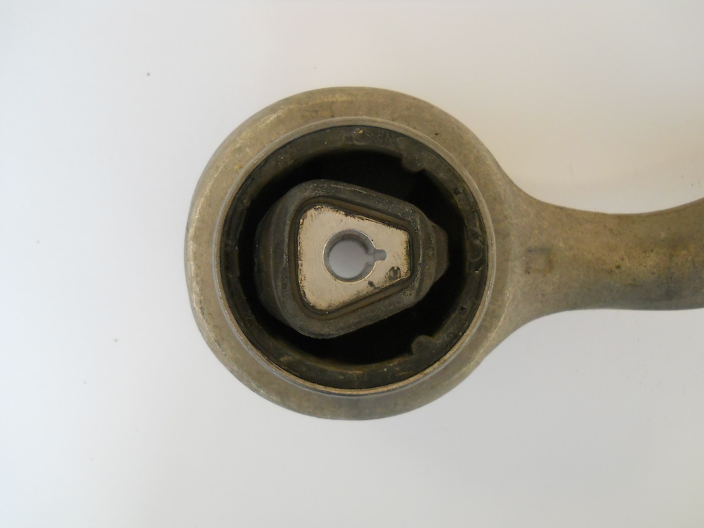
The bushing contains two separate fluid-filled cavities. The hydraulic fluid permits forces to be transmitted through the body of the bushing without contributing to the bushing stiffness. The fluid also supports the relatively thin wall sections, which would otherwise quickly kink, overheat and fail.
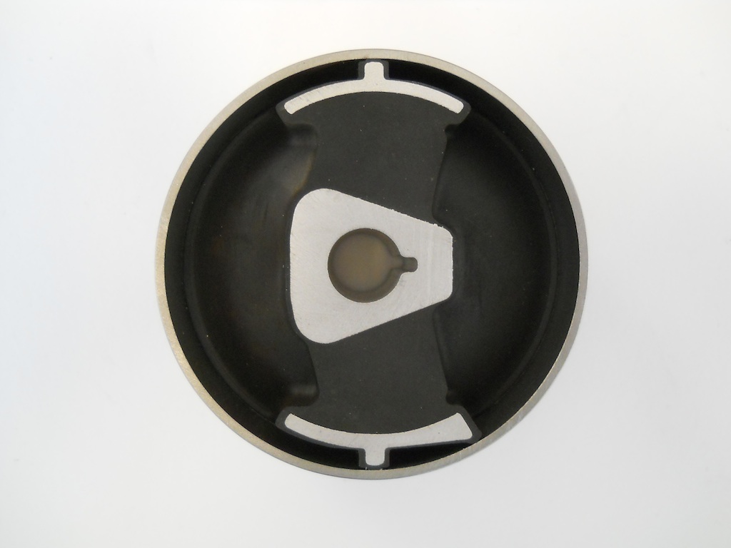
In the above image, the tension loads are horizontal and the bushing is very soft in this direction. The bushing is very stiff in the un-loaded vertical direction, simply to maintain control over the hydraulic cavities.
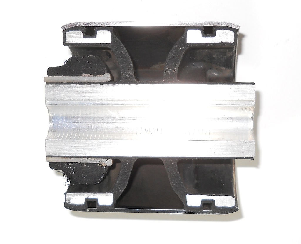
The bushing is soft enough that it is easily deflected by hand over a short range, but then bumpers stiffen up the bushing. The bumper is removed from the right hand side of the above image. The bumpers result in extremely non-linear stiffness characteristics. The initial softness results in a reduction in NVH, and the final stiffening results in appropriate control over wheel position during cornering and braking. In order to characterize the stiffness properties I have measured deflections and loads on an OE tension strut when loaded in the tension direction.

I have repeated the same test with an M3 tension arm, which uses a much simpler concentric-shell rubber bushing.

The results are plotted below:
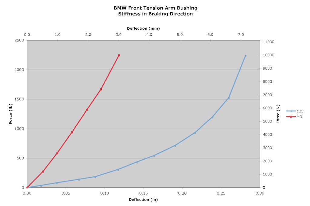
Clearly the M3 tension arm is more concerned with wheel control than NVH.