|
|
|
|
|
| 04-19-2010, 04:21 PM | #67 |
|
New Member
0
Rep 24
Posts |
Thanks Feyd - i was thinking along the same lines. The clamp is "clamped" but under a flashlight it doesnt look like it cut all the way through. I'll see if I can find a smaller clamp than the one that came with the HW kit and try again. Just wanted to confirm i has the right wire (white/green #3 pin). thanks!
|
|
Appreciate
0
|
| 09-09-2010, 02:06 PM | #69 | |
|
Brigadier General
 
279
Rep 3,164
Posts
Drives: Many
Join Date: Feb 2009
Location: North of 7K RPM
iTrader: (1)
Garage List 2020 BMW M2 CS [0.00]
1994 Audi RS2 Avant [0.00] 2021 Audi RS6 Avant [0.00] 1988 BMW E30 M3 [0.00] 2011 BMW 1///M [0.00] 2017 BMW F80 M3 30 ... [0.00] 2018 Porsche 991.2 GT3 [0.00] 2015 Porsche Macan ... [0.00] 1998 Porsche 993 C4S [0.00] 1994 Lancia Delta I ... [0.00] 2008 Audi RS4 [0.00] |
Quote:
If so, I didn't have to remove the A-pillar headliner, you can snake in the wires through/behind it by using a plastic tool (Bavarian Auto has a set of 6 plastic trim removal tools sold in a kit for something like $20, very handy for all kinds of work).
__________________
2011 BMW E82 1///M: AW, all options; Renntech, Akrapovic, Forge, P3, RevoZ CF bits, many mods
1988 BMW E30 M3: Hennarot, S14, stock 2018 Porsche 991.2 GT3: PtS, CXX, LWBS, PCCB 1998 Porsche 993 C4S: Zenith Blue, last aircooled widebody, Bilstein PSS10, Fister II + Fabspeed exhaust 2008 Audi B7 RS 4: Sprint Blue, Audi Exclusive Euro Bucket Interior, Premium+Titanium, many mods |
|
|
Appreciate
0
|
| 09-10-2010, 10:59 AM | #70 | |
|
Brigadier General
279
Rep 3,164
Posts
Drives: Many
Join Date: Feb 2009
Location: North of 7K RPM
iTrader: (1)
Garage List 2020 BMW M2 CS [0.00]
1994 Audi RS2 Avant [0.00] 2021 Audi RS6 Avant [0.00] 1988 BMW E30 M3 [0.00] 2011 BMW 1///M [0.00] 2017 BMW F80 M3 30 ... [0.00] 2018 Porsche 991.2 GT3 [0.00] 2015 Porsche Macan ... [0.00] 1998 Porsche 993 C4S [0.00] 1994 Lancia Delta I ... [0.00] 2008 Audi RS4 [0.00] |
Quote:
__________________
2011 BMW E82 1///M: AW, all options; Renntech, Akrapovic, Forge, P3, RevoZ CF bits, many mods
1988 BMW E30 M3: Hennarot, S14, stock 2018 Porsche 991.2 GT3: PtS, CXX, LWBS, PCCB 1998 Porsche 993 C4S: Zenith Blue, last aircooled widebody, Bilstein PSS10, Fister II + Fabspeed exhaust 2008 Audi B7 RS 4: Sprint Blue, Audi Exclusive Euro Bucket Interior, Premium+Titanium, many mods |
|
|
Appreciate
0
|
| 09-13-2010, 09:43 AM | #71 | |
|
Brigadier General
279
Rep 3,164
Posts
Drives: Many
Join Date: Feb 2009
Location: North of 7K RPM
iTrader: (1)
Garage List 2020 BMW M2 CS [0.00]
1994 Audi RS2 Avant [0.00] 2021 Audi RS6 Avant [0.00] 1988 BMW E30 M3 [0.00] 2011 BMW 1///M [0.00] 2017 BMW F80 M3 30 ... [0.00] 2018 Porsche 991.2 GT3 [0.00] 2015 Porsche Macan ... [0.00] 1998 Porsche 993 C4S [0.00] 1994 Lancia Delta I ... [0.00] 2008 Audi RS4 [0.00] |
Quote:
As far as snaking the wire, here is what I did: I loosened (but not removed) the passenger sunvisor, that simply gives you more space and wiggle room to work the headliner. I have my Escort up by the mirror (it cannot be seen by outsiders as it is behind the dark factory shade of our windshield), so I snaked the wire behind the headliner and down the A-pillar cover, all the way down to the footwell where you can further snake it in to the fuse box. Hope this helps and good luck.
__________________
2011 BMW E82 1///M: AW, all options; Renntech, Akrapovic, Forge, P3, RevoZ CF bits, many mods
1988 BMW E30 M3: Hennarot, S14, stock 2018 Porsche 991.2 GT3: PtS, CXX, LWBS, PCCB 1998 Porsche 993 C4S: Zenith Blue, last aircooled widebody, Bilstein PSS10, Fister II + Fabspeed exhaust 2008 Audi B7 RS 4: Sprint Blue, Audi Exclusive Euro Bucket Interior, Premium+Titanium, many mods |
|
|
Appreciate
0
|
| 02-27-2011, 09:44 PM | #72 |
|
Second Lieutenant
 22
Rep 210
Posts |
2 hours and several hundred curses later
 ... Got it done.. Went the sun visor route and pushed in the clips that way.. Had it all done in about 30 minutes, but then it suddenly stopped working.. Found out the wire tap i was using was for a larger wire(14-16 gauge).. Had to pick up a 10-12.. ... Got it done.. Went the sun visor route and pushed in the clips that way.. Had it all done in about 30 minutes, but then it suddenly stopped working.. Found out the wire tap i was using was for a larger wire(14-16 gauge).. Had to pick up a 10-12.. Needless to say, this thread has helped me greatly.. Hope this bump reaches others and relieves them of the frustrations with this!  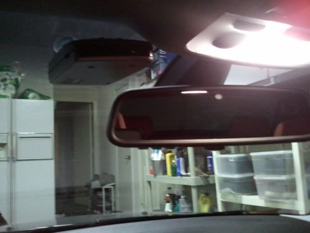 |
|
Appreciate
0
|
| 02-28-2011, 07:29 PM | #73 |
|
Second Lieutenant
22
Rep 210
Posts |
Okay I actually just found something wrong with this just now.. So on the install I tapped into the green and white wire, which apparently is the sunroof.. Now whenever I open my sunroof all the way it turns off the radar detector.. It only turns back on when I close the sunroof.. Also when I just tilt the sunroof it still works but when I close from tilt it power cycles the radar detector..
What could be causing this? Bad ground, wire tap, or what? By the way I grounded into the small screw that the RED arrow is pointing to. Could that be the problem? 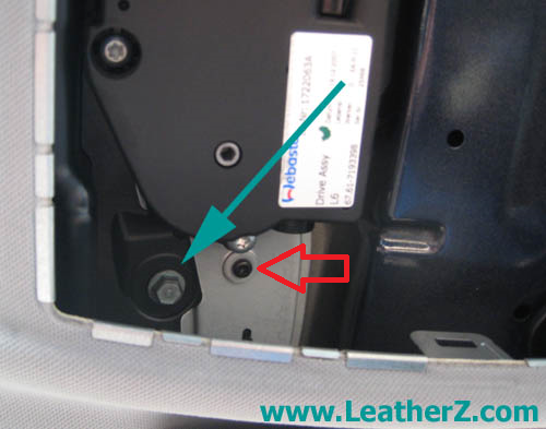 Last edited by Salazar; 02-28-2011 at 07:35 PM.. |
|
Appreciate
0
|
| 04-15-2011, 11:22 AM | #75 | |
|
Lieutenant
137
Rep 536
Posts |
Quote:
 |
|
|
Appreciate
0
|
| 04-15-2011, 12:25 PM | #76 | |
|
Second Lieutenant
22
Rep 210
Posts |
Quote:
__________________
|
|
|
Appreciate
0
|
| 04-22-2011, 08:58 AM | #77 | |
|
Registered
0
Rep 3
Posts |
Quote:
|
|
|
Appreciate
0
|
| 04-22-2011, 10:48 AM | #78 | |
|
Lieutenant
137
Rep 536
Posts |
Quote:
|
|
|
Appreciate
0
|
| 07-30-2011, 11:37 AM | #79 |
|
Lieutenant
7
Rep 443
Posts |
Done, thanks!
Had to use the fingers under the headliner technique, and that ground screw would *defnitely* be hard to get back in.
__________________
Because... grocery getter.  |
|
Appreciate
0
|
| 08-14-2011, 08:13 AM | #80 |
|
Registered
4
Rep 3
Posts |
Just hard-wired an Escort by tapping into the roof control console of a 2011 128i, and just wanted to give some pointers. *To remove the console, try using two old credit cards to push the clips in. *Use the cards as shims and do it one side at a time. *When you push one clip in, push the card in further and leave the card in so that the clip doesn't pop back in when you're working on the other side. *
Also, use the 10 mm bolt (the one with the green arrow in this thread's picture) as the ground and I used the green & white wire on the bigger connector to the left of the one shown in the thread's picture with the green arrow. *I believe this is the power for the mirror's garage door opener. * *I tried the hex bolt with the red arrow as suggested in another picture as an alternative in this thread but it's not a good ground... the voltage drops when the sunroof is opened. Hope this helps! |
|
Appreciate
0
|
| 09-05-2011, 09:41 AM | #81 |
|
Registered
0
Rep 2
Posts |
Hardwire Escort 9500ix Radar Detector in 2009 135i
Motivation and Plan
Desire to have the radar detector without the cord dangling through the occupant space. See existing power cord running from radar detector, attached to top of windshield or right front sun visor, to accessory power supply. Read existing posts, which indicate two general approaches to obtain power for radar detector via option (1) fuse box behind glove box; or, (2) upper center console light/sunroof components. For example,
Select (1). Rationale: (1) is reversible and will have its own dedicated fuse/circuit. (2) has higher risk actions that involve either cutting into existing wires and circuits, or jamming an additional wire into existing circuit and wire receptacle. Preparation Assemble the following tools (details for their use is provided below, throughout the post)
Open and retract glove box for access to fuse box Remove the damper from its attachment to the glove box door (a). Gently push the T-attachment of the damper forward (toward the front of the vehicle), the T-attachment will snap past the detent and release from the door. The glove box will fall under gravity and then stop rotating when the box hits the stops on the left (b) and right (c) sides. Simultaneously, press stop at (b) to the left and (c) to the right to release the glove box and expose the fuse box. The T-attachment is shown at (d). Remove fuse map card (e). View fuse box (f) and consider placing a small flashlight therein to illuminate this work area. The fuse map card front and back side are shown below. The question, "Which fuse do I use?" was the most difficult question during this entire process, and I would welcome and appreciate someone with expertise in this area to comment (more on this question later). Preparation of circuit I went to AutoZone, and purchased a fuse tap, a box of 10 Amp blade fuses (also referred to as mini-fuses), 18 gauge wire, and a box of assorted quick disconnects. Why did I purchase 10 Amp rated fuses? Because I decided to plug into the fuse box at slot (5), which is currently unused in my vehicle and is rated, per the fuse map card, at 10 Amp. I was confounded by this step. This is the step that I mentioned above that I am imploring others with domain knowledge to comment and educate me. Other posts have indicated they elected slot (8), which is a 20 Amp circuit. My rationale for not electing slot (8) was two-fold:
Additionally, I wanted the circuit to be off when the engine was off. But I lacked data at this point for slot (5), since it was not listed on the front of the fuse map card. So, my selection of slot (5), to some degree, now became a leap of faith at this point, trial and error.... I started with the Escort direct wire connection, which has three end point connections that I'll refer to as to-detector (phone style appearance), supply (flat metal connection surrounded by blue translucent plastic insulation), and ground (circular halo-shaped). I connected the supply to a quick disconnect (photo of box of disconnects above). I then utilized an approximately 3 inch length of 18 Gage wire as a bridge wire. Why did I choose 18 Gage wire? I tried to match the thickness of wires present on the other wires I was attaching to, in the hopes of minimizing any impedance step-offs between wire connection sites. I stripped approximately 1 cm of insulation from each end of the bridge wire. I pressed the exposed wiring of one end into the quick disconnect and crimped the connection. I then pressed the remaining end of exposed wiring into the fuse tap connection (surrounded with the blue cylindrical opaque insulation), and crimped this connection. Finally, I placed red electrical insulating tape, spiraled in a helical pattern, around both connection sites. I placed two fuses (10 A rating for each) into each of of the two open slots on the fuse tap. Next, I wanted to test the circuit's viability. Let's make sure everything turns on and off properly, before we start routing the wire from the fuse box to the radar detector, a process (seen later) that will involve removing part of the A-pillar trim. I plugged in the fuse tap to (currently open) slot (5), and prepared the ground to fit around the bolt (g). The out-of-focus item (f) is a head-mounted flashlight I used to illuminate the fuse box space. The diameter of the hole on the ground connection was less than the diameter of the bolt, so I used wire snips to cut full-through the thickness, widened the ground connection diameter, and slipped the ground connection around the bolt, as shown below. Then I reconnected the bolt to secure the ground connection. I started the engine. The leap of faith worked (so far)! The radar detector fired up right with the engine, the radio, and all other start up functions. I powered off the engine. I radar detected went off. Great! I turned on the accessory power without the engine (e.g., radio only), and the radar detector did not come on. Great! This is exactly the specification I wanted. So far, so good! Routing the wiring from the radar detector to the fuse box I next used a T30 star head on a ratchet to remove two screws (m, n) that secure, in part, the lower trim cover on the instrument panel adjacent to the right front occupant foot well. In addition to the two screws, there is a press-fit connector (o) that routes through the center console trim and anchors thereunder. This connector (o) proved very difficult to reassemble, and took longer than any other step in the entire process. This trim piece will then fall slightly with gravity (or with a gentle pull in addition to gravity). This trim piece has one slot-type anchor near the fire wall, near the back of the piece. To dislodge this piece from the instrument panel, pull gently toward the rear of the vehicle. Next, prepare the A-pillar trim area. I elected to remove the A-pillar trim to allow routing of the wire concurrently with other existing wires under the A-pillar trim. Some people have indicated they simply stuffed the wire behind the A-pillar trim. I was concerned that stuffing the wire behind the A-pillar trim might have potential to interfere with the deployment path of the side curtain air bag. So, I avoided such "stuffing" methods concerning the A-pillar. Instead, I took a small, flat head screw driver and gently pried and popped off the "AIRBAG" plastic cover. Unfortunately, at this step, I did damage the cloth covering a small bit by snagging two or three threads in the cloth. The thread snags are barely perceptible. After the cover is removed, a small screw is present. Unscrew. You are left with the A-pillar trim piece being secured by only plastic anchors behind the trim. Carefully, slowly, and gently grasp the A-pillar trim near the midsection and pull up toward the roof and back toward the rear of the car. This is a tough step since the attachment is a snug fit. Go slowly, be patient (tough for BMW drivers, I know!!!!). Jiggle and nudge. The trim piece will then come free from the A-pillar. Notice the five attachment points: The two slots at the base, the two slip-fits on the midsection, and the metal housing for the screw that was removed. Appreciate this connection anatomy, as it will facilitate reassembly. Next, mount the radar detected in the desired location. For me, it is via a clip to the right front sun visor. I understand there is considerable debate about radar detector placement, though it is not my goal to add to that debate in this post. I actually did use the "stuffing" method (here only, not at the A-pillar) to route the wire from the radar detector, under the head liner, and to the top of A-pillar. To stuff, I used the fuse map card, mentioned above. Others have reported using a kitchen spatula to stuff. I then ran the wire down the A-pillar concurrently with the existing wires. I attached the new wire to the existing wires with zip ties. I ran the wire down the A-post, placing the wire behind the large, pliable rubber door seat. At the junction of the lower instrument panel, I ran the wire from the door seal, from right to left across the trim seam, to the space that opens to the under side of the fuse box. Gather the balance of the cord and place neatly into the fuse box. Finally, reassemble everything. Enjoy! Other people, using methods different from what I have described here, have reported their radar detector not working or restarting upon open or close of the sunroof. So far, I have encountered no problems in the two days of driving post-installation. The install took me about 5 hours from start to finish, and included dinner and other distractions. Thank you to the other people who took time to post instructions and photographs. I learned a great deal from you, and I appreciate your generosity. Finally, I welcome all comments, but am particularly keen on learning about the electrical steps, if someone has insights they would like to share. Last edited by Eyes Up; 09-05-2011 at 02:53 PM.. |
|
Appreciate
0
|
| 09-08-2011, 12:51 AM | #82 |
|
Captain
194
Rep 645
Posts |
Don't mean to Hi- jack this thread but I really could use help on this issue. I hardwired my V1 to my car and it was pretty easy. I'm hardwiring my XM Onyx radio to the car so I don't have to look at wires anymore. They sent me this hardwire kit and Im oblivious as to where to install the two split wires at the end.Below is a pic:
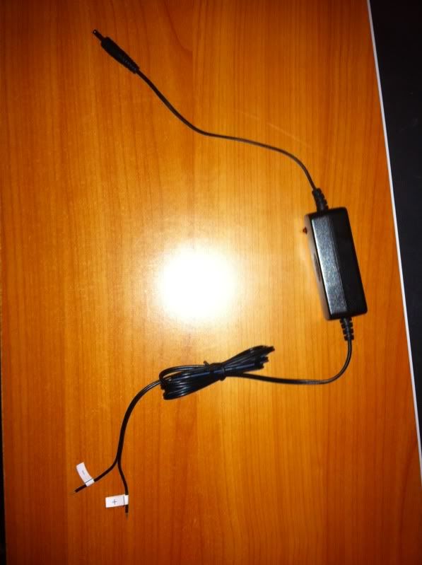 Last edited by SixBanger; 09-08-2011 at 12:52 AM.. Reason: pic error |
|
Appreciate
0
|
| 09-13-2011, 02:47 PM | #83 | |
|
Boooooost!
5
Rep 73
Posts |
Quote:
The circuits in the fuse box are rated buy what uses it and what the wires going to that point can support. Normally a standard power outlet will use a 10-20 amp fuse as that allows you to plug in devices that may draw some decent current. But keep in mind that most electronics already have small glass type fuses in the power adapter that is a very low rated fuse. Just my two cents. Oh, and nice and very detailed write-up!!
__________________
09 135i, A6, Monaco/Coral Red, M-Sport pkg, Premium pkg, Hi-Fi sound,
Last edited by 135nRXP; 09-13-2011 at 03:08 PM.. |
|
|
Appreciate
0
|
| 09-25-2011, 06:43 PM | #84 | |
|
New Member
0
Rep 7
Posts |
Quote:
|
|
|
Appreciate
0
|
| 12-23-2011, 01:26 PM | #86 |
|
New Member
3
Rep 13
Posts |
Thank you to Eyes Up
Eyes Up,
Just wanted to say thank you for the post and detail direction. I liked your power solution and followed as per your instruction. Works like a charm. Few things I did differently is that I started to pull the wire from below instead of starting from top. I found it was easier to move the wire around the door jam. I also had remote mute, so it was the right way to start for me. Also, I did take off the AirBag cover and unscrew the bolt, that was enough for push the wire through the panel ( didn't really wanted to take the whole cover off). Worked well. Thank you again.  For placement of my 8500 X50, I built a custom bracket so that I don't have any visiable sign of a detector on my windshield. I know it's probably reduced the ability for rear coverage, but I was more concerned about someone breaking into the car. Bracket was very easy to make. Lowes has thin steel plates which I cut with a my dremel to fit the unit's holder slot and rest is just bending 90 degrees and spray paint. LOWES plate was ($0.53). SKU 98921 TP15 1x5 TIE PLATE. Picture attached. |
|
Appreciate
0
|
| 01-06-2012, 10:37 PM | #88 |
|
S58 Love
544
Rep 447
Posts
Drives: 2023 M4 Competition xDrive
Join Date: Apr 2011
Location: OR
|
Thanks AndyM..... Less than 30 minutes start to finish.
__________________
MAC
Current: 2023 G82|BG over BLK Prior: 2008 N54 E82|AW over CR Also: FJ60, Volvo Recharge |
|
Appreciate
0
|
Post Reply |
| Bookmarks |
|
|